| Issue |
Int. J. Metrol. Qual. Eng.
Volume 12, 2021
Topical Issue - Advances in Metrology and Quality Engineering
|
|
|---|---|---|
| Article Number | 24 | |
| Number of page(s) | 9 | |
| DOI | https://doi.org/10.1051/ijmqe/2021022 | |
| Published online | 01 October 2021 | |
Research article
Analysis of metrological characteristics of elbow flowmeter under rotating state
1
Institute of Electrical Engineering of Chinese Academy of Sciences, Beijing 100190, China
2
University of Chinese Academy of Sciences, Beijing 100049, China
3
Dongfang Electric Machinery Co., Ltd, Deyang, Sichuan 618000, China
* Corresponding author: This email address is being protected from spambots. You need JavaScript enabled to view it.
Received:
31
March
2021
Accepted:
23
August
2021
Abstract
The application of elbow flowmeter in rotary equipments is beneficial to reduce the pipeline complexity. However, the intervention of centrifugal acceleration will lead to the change of metrological characteristics of elbow flowmeter. Based on the analysis of the differential pressure formation mechanism of the environmental acceleration on the elbow flowmeter, the calculation formula of the flow rate measurement with the elbow flowmeter in the rotating state is derived, and the fitting method of the discharge coefficient is put forward. The CFD method was used to analyze the internal flow field of the elbow flowmeter under rotating state, summarize the pressure distribution characteristics of the pipe wall, and verify the feasibility of the discharge coefficient fitting strategy by simulation. The results show that for the elbow flowmeters with diameters of 10 mm and 15 mm and the radius to diameter ratio of 1.5, as long as the water flow rate is between 1.5 m/s and 5 m/s, the measurement accuracy can be guaranteed to be above 4%.
Key words: Metrological characteristic / elbow flowmeter / centrifugal acceleration / differential pressure / discharge coefficient
© Y. Wang et al., Published by EDP Sciences, 2021
 This is an Open Access article distributed under the terms of the Creative Commons Attribution License (https://creativecommons.org/licenses/by/4.0), which permits unrestricted use, distribution, and reproduction in any medium, provided the original work is properly cited.
1 Introduction
In the compact rotating equipment, the flowmeter not only has limited installation space, but also bears strong centrifugal force and certain mechanical vibration. The conventional design is difficult to meet such installation requirements. For elbow flowmeter without movable parts, we can directly replace the bend in the pipeline with high reliability. Moreover, the introduction of elbow flowmeter is useful for simplifying the installation structure as well as restraining additional flow resistance, and demonstrating outstanding superiority in this scenario [1]. Figure 1 describes a typical design. The red part is a section of tube in a rotating equipment, and the elbow in the lower right corner is elbow flowmeter. For clarity, other irrelevant accessories are hidden in the figure. In this case, the reliability of turbine flowmeter under high-speed rotation cannot be guaranteed because of the existence of movable parts; the head of thermal flowmeter and electromagnetic flowmeter are heavy, which is difficult to meet requirements of rotor dynamic balance. In addition, the limited space on the rotor cannot provide enough straight pipe space to meet the requirements of most flowmeters. To use elbow flowmeter instead of the previous bend in the pipeline is one of the most feasible schemes, which does not require the change of the original pipeline design and has the characteristics of no movable parts used for promoting the reliability in the environment of high-speed rotation and vibration.
However, the metrological characteristics of elbow flowmeter in rotating state have not been studied, and the measurement formula is not clear. In this paper, the metering principle of the rotary elbow flowmeter is analyzed, the calculation formula for flow rate of the elbow flowmeter in the rotating state is derived, and the discharge coefficient fitting method of the elbow flowmeter in the rotating state is proposed. Finally, the method is verified by the way of computational fluid dynamics.
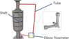 |
Fig. 1 Structure Schematic Diagram of One Rotating Equipment. The red part is a section of tube in a rotating equipment, and the elbow in the lower right corner is elbow flowmeter. |
2 Materials and methods
2.1 Research methods and status of metrological characteristics of elbow flowmeter
Elbow flowmeter is a kind of differential pressure flowmeter. Therefore the metering principle for it is very different from Orifice, Venturi and other differential pressure flowmeters. Due to the centrifugal force, the pressure of the fluid flowing through the elbow on both sides of the pipe will be different. There is a positive correlation between the pressure difference and the average velocity of the fluid. By measuring the pressure difference between the inside corner and outside corner of the elbow, the working fluid velocity in the pipe can be calculated.
After Jacobs and Sooy proposed the concept of elbow flowmeter in 1911, Lansford and Addison proposed the free vortex theory and forced vortex theory of elbow flowmeter [2,3]. Then, Taylor, Robertsondui and Spink summarized the previous research results and formed empirical formulas [4]. J.W. Murdock not only studied the influencing factors of discharge coefficient, but also compared elbow flowmeter with standard differential pressure type flowmeters such as Orifice, Nozzle and Venturi tube [2,5]. Taylor studied the secondary flow in a rectangular bend [6]. In the past 20 years, the advantages of low cost and high reliability of elbow flowmeter have attracted many scholars again. Einhellig [7], Deneux [8], Yuan [9], Lannes [10] and Zhang Lin [11] introduced concept of an elbow flowmeter to various application contexts.
Some new measurement methods such as PIV and numerical simulation technology are also applied in recent research. In the aspect of experimental research, Ikarashia and Taguchi analyzed the influence of curvature on the flow field [12–15]. Visualization method is introduced into Fujisawa's study about the mass transfer characteristics in the elbow [16]. In terms of numerical analysis, Wang [17], Zhu [18], Qiao [19–21], Mazumder [22] simulated the two-phase fluids in the elbow by CFD. Gogolin shows relationship of cross section shape and the flow characteristics [23]. Deneux [8] and Rawat r [24] pointed that a validated CFD method can accurately predict the flow field in the elbow flowmeter.
The widely accepted formula for the mean velocity calculation in the elbow flowmeter is as follows: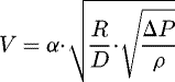 (1)
(1)
Or (2)
(2)
where, V is the average velocity of the working medium in the elbow, α is the discharge coefficient, R is the radius of the center line of the elbow, D is the inner diameter of the elbow pipe, ΔP is the pressure difference between inside and outside of the elbow, ρ is the fluid density in the elbow.
Due to the complexity of the flow in the elbow, there are many factors that will affect the discharge coefficient of the elbow. So far, the discharge coefficient can only be obtained by flow calibration experiments [1]. In the conventional application, the gravity pressure difference caused by the height difference between the inner and outer pressure taps of the elbow is so small that can be ignore or averted. When the elbow flowmeter is used in rotating state, the environmental acceleration will have an important influence on the pressure distribution of the flow field. However, the research of the elbow flowmeter in acceleration field is still in a blank.
2.2 Theoretical analysis of the metrological characteristics of elbow flowmeter under rotating state
The biggest difference between the application of the elbow flowmeter in rotating equipment and conventional application is the introduction of centrifugal acceleration caused by rotation. In Figure 2, a topological structure of the elbow meter, in which the outlet is vertical upward, is stated. The figure shows an elbow flowmeter with the revolving speed of Nr. L is the distance between bend curvature center o and rotating shaft. V is the average flow velocity of the fluid in pipe. g is the acceleration of gravity. ac is the centrifugal acceleration outward along the radius. Sign for angle, θ, is the angle between the axis of the pressure tap and the direction of gravity, and also the rotation angle of the pressure tap relative to the inlet of the elbow. For this type of flowmeter, the differential pressure is defined as the difference of the pressure measured at the inside and outside position of one elbow: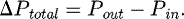 (3)
(3)
The differential pressure is composed of three parts. The centrifugal acceleration generated by the rotation of the elbow around the shaft has a component along the pressure tap axis. This component acts on the fluid contributes to the pressure difference ΔPa, which is named revolving speed term. The component of gravity acceleration acting on the fluid along the axial of the pressure tap produces a pressure difference ΔPg, which is named gravity term. The centrifugal acceleration caused by the fluid turning in the elbow come into being the pressure difference ΔPt along the bending radius (i.e. the pressure tap axis), which is called fluid velocity term in the following parts.
The revolving speed term is independent from the flow velocity of the working medium. Only the centrifugal acceleration generated by the rotation of the equipment should be integrated along the axis of the pressure tap: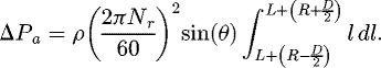 (4)
(4)
This equation can be simplified to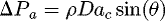 (5)
(5)
where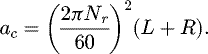 (6)
(6)
The gravity term is the same as the rotational speed term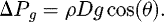 (7)
(7)
Assuming that the velocity in the elbow is uniform, according to Newton's second law, the velocity term is: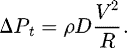 (8)
(8)
Because the velocity distribution of fluid in the elbow is not uniform actually, the calculation result of velocity term will be different from the truth value. Therefore, the relationship between the pressure difference measured at the pressure tap and various influencing factors are as follows: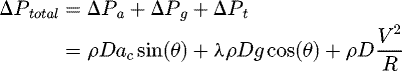 (9)where, λ = 1 when the outlet of the elbow is upward, λ = −1 when the outlet of the elbow is downward, λ = 0 when the gravity effect can be ignored.
Explanation of λ: in Figure 2, when the outlet of the elbow is vertical upward, the position of the pressure tap on the outer walls of the elbow is lower than that on the inner walls in the vertical direction, and the direction of the gravity term is the same as the other two centrifugal accelerations, so that the gravity term is positive. If the elbow shown in Figure 2 is turned over along the horizontal line, then the outlet of the elbow is vertical downward, direction of gravity term is opposite to the other two centrifugal accelerations and make the value negative. When the elbow outlet is horizontal, or in a situation that gravity has little effect on the differential pressure, the gravity term is 0.
Considering factors ignored in the simplified calculation, such as Reynolds number, pipe inner face roughness, secondary flow etc., a discharge coefficient should be introduced into the calculation formula of the average flow velocity of fluid in the rotating elbow flowmeter. According to the traditional custom, we can formalize formula (9) into formula (10) with reference to formula (1). The formula has only one discharge coefficient, and the fitting process can be relatively simpler.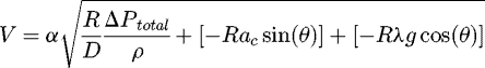 (10)
(10)
However, because the mass transport process of the working fluid in most sections of the elbow tends to the inner region [18] while flowing past the bend, the true value of the velocity term in the equation is smaller than the calculated value. At low flow rate, even the radicand in equation (10) is negative, resulting in the failure of the formula. In order to ensure the validity, it is necessary to take more accurate corrections to each item in the formula.
By means of multiple regression, according to the actual measured differential pressure value, the three terms from equation (9) are adjusted by the discharge coefficient αa, αg and αt respectively. (11)
(11)
Through the real flow calibration, the calculation formula for the velocity V in the pipe can be obtained after calculating three discharge coefficient values.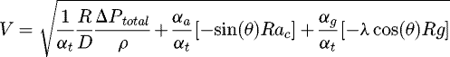 (12)
(12)
The calculation formulas for mass flow rate and volume flow rate of the elbow flowmeter under rotating state are as follows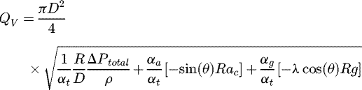 (13)
(13)
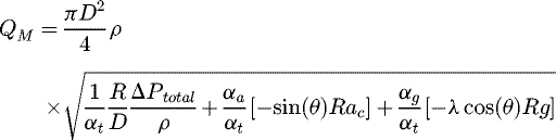 (14)
(14)
where, QV is volume flow rate; QM is mass flow rate.
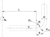 |
Fig. 2 Geometric Dimension of the Elbow Flowmeter for theory. The outlet of elbow flowmeter is vertical upward. The elbow flowmeter rotates at the revolving speed of Nr. L is the distance between bend curvature center o and rotating shaft. V is the average flow velocity of the fluid in pipe. g is the acceleration of gravity. ac is the centrifugal acceleration outward along the radius. Sign for angle, θ, is the angle between the axis of the pressure tap and the direction of gravity, and also the rotation angle of the pressure tap relative to the inlet of the elbow. |
2.3 Simulations
Due to the strong disturbance from centrifugal and Coriolis force on the flow, the elbow flowmeter under rotating state can accurately get the relevant discharge coefficient only through the experimental calibration. In this paper, according to the rotating equipment shown in Figure 1, a fluid model close to the real size is established, and the CFD software is used for numerical calculation. The calculation results verify the feasibility of the above discharge coefficient acquisition method.
2.3.1 CFD model
Two kinds of bend pipes with inner diameter of 10 mm and 15 mm, the radius to diameter ratio of the elbow (R/D) equals to 1.5 were selected for analysis. In the two analysis groups, the straight pipe has the same inner diameter as the bent pipe.
Considering that the rotation increases the complexity of the flow field, a fluid simulation model including almost the whole flow path on the rotating equipment is established according to the physical scene (Fig. 3). The RNG k-ε turbulence model is used to obtain a better solution accuracy near the wall and to track the pressure change near the wall.
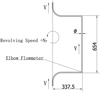 |
Fig. 3 Topology of 3D fluid simulation model (mm). |
2.3.2 Boundary condition
The present literatures show that the wall roughness has little effect on the metrological characteristics of the elbow flowmeter, so the wall of in this model is set as smooth and non-slip. Inlet velocity and outlet pressure are used as boundary conditions. The inlet flow velocity starts from 0.5 m/s and stepwise increases to 5 m/s with the interval of 0.5 m/s. The rotational speed of the model is given by revolutions per minute (r/min), and gradually increases to 500 r/min at intervals of 50 r/min from motionless.
2.3.3 Grid independence verification
After boundary layer is modeled, and the grid independence is verified. The number of optimized grids is 1.5 times, 2 times and 3 times of the original grid. The calculated differential pressure at θ = 45° position is compared with the measured differential pressure by previous experiments in Table 1. It is considered that the number of grid nodes in the order of 5×10⁵ can meet the calculation requirements.
Grid independence verification.
2.3.4 Calculation setup
The pressure taps are set at three locations (22.5°, 45° and 67.5° count from the inlet), where the 90° elbow is divided into four equal parts, to obtain the differential pressure values (denoted by ΔP22.5°, ΔP45° and ΔP67.5°) under different working conditions. As soon as the simulation results are obtained, such differential pressures were treated as the dependent variable to calculate the discharge coefficients.
3 Results and discussion
3.1 Flow velocity and pressure distribution
Figure 4 compares different velocity distribution on the central plane of the fluid and the secondary flow distribution on multiple cross sections under the working conditions of revolving speed from static to 400 r/min and velocity from 1 m/s to 5 m/s. It can be seen that: (1) Compared with other sections, the secondary flow is always the smallest at the 45° section of the elbow, no matter the states if static or rotating; (2) under rotating condition, the secondary flow in the elbow no longer distributes symmetrically with respect to the central plane of the elbow, but deflects to one side, and even turns into annular flow along the inner wall of the pipe, and the fluid advances in a spiral shape; (3) with the increase of rotating speed, the velocity field at the elbow tends to be uniform. The great change of secondary flow distribution during rotating is due to the introduction of large Coriolis force caused by rotation, which is much greater than that caused by fluid turning in the elbow.
The uneven flow velocity distribution on the inner interface of the elbow will dramatically affect the calculation accuracy for the velocity term. For further analysis of the relationship between the nonuniformity of velocity distribution in the elbow and the rotating speed, as well as the influence of flow velocity, the flow uniformity coefficient δ, defined by TAO Hongge [25], in the pipe section is defined. The closer δ is to 1, the more uniform the velocity distribution is.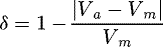 (15)where, Va is the area weighted average velocity, Vm is the mass weighted average velocity.
The variations of the flow uniformity coefficient δ of each section in the pipe changes with different flow velocity is shown in Figure 5. It shows again that the flow uniformity increases with the increase of revolving speed no matter with the tapping positions. Under the same revolving speed, the flow uniformity changes in the opposite direction from the flow velocity.
The differential pressure of elbow flowmeter (diameter is equal to 10 mm) in a variety of conditions are stated in Figure 6. It can be seen that the increasement of differential pressure is growing faster than that of flow velocity, and only the differential pressure measured at 67.5° position can keep monotonically increasing. ΔP45° and ΔP67.5° decrease firstly and then increase during the low revolving speed range. Some researchers [26,27] present an idea that the secondary flow is proportional to the flow velocity and plays an important role in pressure distribution. The pressure drop increases with velocity in the laminar flow region, but may experience a period of decrease in the transition and turbulence regions. It might be the reason for those lines represent non-monotonicity. Because in the situations of relative low revolving speed, the fluid velocity term take a larger proportion in the total differential pressure, hence the influence of the velocity field on the pressure field is easier to be observed. Figure 7 shows this pressure feature again in contours.
 |
Fig. 4 Velocity Field and Secondary Flow Distribution under Different Conditions. |
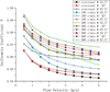 |
Fig. 5 Variation of Flow Uniformity Coefficient. The variation of the flow uniformity coefficient δ of each section in the pipe changes with different flow velocity. |
 |
Fig. 6 The change of differential pressure for each position. The differential pressure of elbow flowmeter (diameter is equal to 10 mm) in a variety of conditions and different taps. |
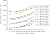 |
Fig. 7 Differential Pressure when Inlet velocity is 5 m/s. |
3.2 Extraction of discharge coefficient
3.2.1 Low-flow measuring characteristics
Differential pressure ΔP22.5°, ΔP45° and ΔP67.5° are extracted at different speeds situation and used in equation (10) to obtain uncorrected flow velocity, then marked with the color of data points in Figure 8. The black square points in the figure indicate that the part within the root sign in equation (10) is negative under this condition, and the calculation formula is not available. It can be seen that, when the flowmeter is in static state (the revolving speed is 0), the calculation results of the whole revolving speed and velocity range are of little deviation. While, in the low velocity and high revolving speed area, the flow velocity in the bend cannot be calculated according to the formula (10). The reason is that, with the increase of rotating speed, the influence of environmental acceleration, especially centrifugal acceleration, on the pressure distribution increases rapidly, so that the velocity term is less than the sum of revolving speed term and gravity term. With the increase of the fluid velocity, the velocity term increases, while the acceleration environment remains unchanged at the same speed. When the velocity term is greater than the sum of the revolving speed term and the gravity term, equation (10) make sense, otherwise the equation will be false.
In the condition of stationary, according to the differential pressure values collected from different position, the relative error between calculation result and the value given at the inlet boundary are shown in Figure 9, and refers to the percentage deviation between the calculated result and the true value. It can be seen that as flow velocity increases the relative error decreases and tends to be stable. On one hand, with flow velocity increases, the velocity distribution on the elbow section becomes more and more uneven, and the value of velocity calculated using average velocity from equation (8) is lower and lower than true value. On the other hand, the relative error in the low velocity region changes dramatically, which will result in the error of velocity calculation formula much higher in low flow velocity region. The low flow velocity range should be abandoned when fitting formula, which means, a certain lower range limit should be set for the elbow flowmeter.
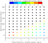 |
Fig. 8 Uncorrected Calculated Flow Velocity Compared with True Value. |
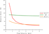 |
Fig. 9 The Relative Error of The Uncorrected Velocity calculated in Stational State. The relative error refers to the percentage deviation between the calculated result and the true value which has been given at the inlet boundary. |
3.2.2 Fitting of discharge coefficient
Since in the low flow velocity area the fitting error of discharge coefficient is large, when fitting the discharge coefficient, the data with the inlet velocity less than 1.5 m/s is discarded. Differential pressure values are collected at the position of 22.5°, 45° and 67.5° of the elbow, and the discharge coefficients of each group are obtained by regression analysis to the two specifications of the elbow flowmeter. Then a statistical analysis of the relative error of the modified flow rate calculation is conducted, and the results are summarized in Table 2, from which we can see that: (1) the fitting precisions of the discharge coefficients at three pressure measuring positions are close, and the relative error after fitting process is mostly below 4%; (2) the measurement results of 22.5° pressure tap are the most unstable; (3) the measurement results of 67.5° pressure tap are the most stable; (4) the more the pressure tap moves downstream, the smaller the relative error of measurement; (5) the correction factor αa of revolving speeds are all less than 1 at different pressure positions; (6) The correction factor αt of flow velocity are all close to 1 at the same pressure position; (7) for elbow flowmeters with same radius to diameter ratio, even if the inner diameters are different, as long as the pressure measuring tap is set at the middle and downstream positions of the elbow, the same correction coefficient can be used for measurement, and the error is within 5%, besides, the measurement results are generally higher.
As the elbow flowmeter with 45° pressure tap has no direction requirement, it is recommended to be used in practical application. According to the discharge coefficients derived from differential pressure fitting at 45° position, the velocity calculation of the flowmeter with 10 mm diameter is carried out and the result is shown in Figure 10. The relative errors of the calculated values are indicated by color in the figure. It can be seen that the differential pressure is positively related to flow velocity and revolving speed, and the relative errors calculated under low velocity range are larger.
Discharge coefficients and prediction accuracy.
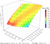 |
Fig. 10 Measurement Error of the Elbow Flowmeter. According to the discharge coefficients derived from differential pressure fitting at 45° position, the velocity calculation of the flowmeter with 10 mm diameter is shown by the point. The color means the relative error. |
4 Conclusions
In this paper, the metrological characteristics of elbow flowmeter in rotating state are analyzed by both theoretical analysis and CFD simulation. We have derived a new calculation formula of the flow rate and a discharge coefficient fitting strategy, which can be credibly used in the measurement of flow rate in the rotating tube to a certain extent. The results show that elbow flowmeter is a suitable type of instruments in rotating machinery because of high reliability and certain accuracy. In the application scenarios which are involved in flow measurement under rotating state, such as liquid-cooled rotor of generator and centrifuge for rotating distillation, elbow flowmeter has the advantages of saving space and reducing cost. However, like other flowmeters, elbow flowmeters are not good for very small flow metering. Due to the current research conditions and application requirements, the metering characteristics of the rotary elbow flowmeter at higher flow rates have not been studied. The flow rate characteristics of the fluid under higher flow velocity in the elbow flowmeter should be further explored in the later work.
Acknowledgments
This work was supported by Dongfang Electric Machinery Co., Ltd for the study of rotor cooling.
References
- S. Basu, Plant Flow Measurement and Control Handbook (Academic Press, 2019) [Google Scholar]
- J.W. Murdock, C.J. Foltz, C. Gregory, Performance characteristics of elbow flowmeters, J. Basic Eng. 86, 498–503 (1964) [CrossRef] [Google Scholar]
- W.M. Lansford, The use of an elbow in a pipe line for determining the rate of flow in the pipe, University of Illinois Engineering Experiment Station bulletin 289 (1936) [Google Scholar]
- D. Taylor, M. Mcpherson, E. Meier, Elbow meter performance [with discussion], J. Am. Water Work Assn. 46, 1087–1095 (1954) [CrossRef] [Google Scholar]
- R.H. Moen, Discussion: Performance characteristics of elbow flowmeters, J. Basic Eng. 86, 504–505 (1964) [CrossRef] [Google Scholar]
- A. Taylor, J. Whitelaw, M. Yianneskis, Curved ducts with strong secondary motion: velocity measurements of developing laminar and turbulent flow, Fluids Eng. Trans. ASME 104 (1982) [Google Scholar]
- R.F. Einhellig, C. Schmitt, J. Fitzwater, Flow measurement opportunities using irrigation pipe elbows, Hydraulic Measurements and Experimental Methods pecialty Conference (HMEM) 2002 (2002) [Google Scholar]
- O. Deneux, M. Arenas, CFD and Metrology in Flowmetering: Rcs Flow Measurement with Elbow Taps and Its Uncertainty, International Congress of Metrology (2013) [Google Scholar]
- B.Z. Yuan, S. Nishiyama, M. Fukada et al., Hydraulic Design Procedure for Bypass Flow Meters Using a Pipe Bend, Transactions of the Asae (2003) [Google Scholar]
- D.P. Lannes, A.L. Gama, T.F.B. Bento, Measurement of Flow Rate Using Straight Pipes and Pipe Bends with Integrated Piezoelectric Sensors, Flow Meas. Instrum. 60, 208–216 (2018) [CrossRef] [Google Scholar]
- L. Zhang, X. Wu, M. Li et al., Optimization Research of Elbow Flow Meter Design with Alterable Measurement Range, Hedongli Gongcheng/Nuclear Power Engineering 38, 145–148 (2017) [Google Scholar]
- Y. Ikarashi, T. Uno, T. Yamagata et al., Influence of Elbow Curvature on Flow and Turbulence Structure Through a 90° Elbow, Nucl. Eng. Des. 339, 181–193 ( 2018) [CrossRef] [Google Scholar]
- Y. Ikarashi, N. Fujisawa, Mass Transfer Measurements and Flow Separation Behavior in a 90° Short Elbow, Int. J. Heat Mass Transf. 136, 1106–1114 (2019) [CrossRef] [Google Scholar]
- S. Taguchi, Y. Ikarashi, T. Yamagata et al., Mass and Momentum Transfer Characteristics in 90° Elbow Under High Reynolds Number, Int. Commun. Heat Mass Transf. 90, 103–110 (2018) [CrossRef] [Google Scholar]
- Y. Ikarashi, S. Taguchi, T. Yamagata et al., Mass and Momentum Transfer Characteristics in and Downstream of 90° Elbow, Int. J. Heat Mass Transf. 107, 1085–1093 (2017) [CrossRef] [Google Scholar]
- N. Fujisawa, T. Takizawa, T. Yamagata, Comparative Study of Mass Transfer Distributions and Oil-flow Visualizations with Image Analysis on Long and Short 90° Elbows, Exp. Therm. Fluid Sci. 123, 110332 (2021) [CrossRef] [Google Scholar]
- Z. Wang, R. Örlü, P. Schlatter et al., Direct Numerical Simulation of a Turbulent 90° Bend Pipe Flow, Int. J. Heat Fluid Flow 73, 199–208 (2018) [CrossRef] [Google Scholar]
- H. Zhu, J. Jing, X. Yang et al., Numerical simulation of the oil-water two-phase flow in horizontal bend pipes, vol 158 of Computer Science for Environmental Engineering and EcoInformatics. CSEEE 2011, Communications in Computer and Information Science. Springer, Berlin, Heidelberg (2011) [Google Scholar]
- Qiao, S. Kim, Air-water two-phase bubbly flow across 90° vertical elbows. Part I: Experiment, Int. J. Heat Mass Transfer 123, 1221–1237 (2018) [CrossRef] [Google Scholar]
- S. Qiao, R. Kong, S. Kim, Air-water two-phase bubbly flow across 90° vertical elbows. Part II: modeling, Int. J. Heat Mass Transfer 123, 1238–1252 (2018) [CrossRef] [Google Scholar]
- S. Qiao, W. Zhong, S. Wang et al., Numerical simulation of single and two-phase flow across 90° vertical elbows, Chem. Eng. Sci. 230, 116185 (2021) [CrossRef] [Google Scholar]
- Q. Mazumder, V.T. Nallamothu, F. Mazumder, Comparison of characteristic particle velocities in solid-liquid multiphase flow in elbow, Int. J. Thermofluids 5–6, 100032 (2020) [CrossRef] [Google Scholar]
- A. Gogolin, M. Wasilewski, G. Ligus et al., Influence of geometry and surface morphology of the U-tube on the fluid flow in the range of various velocities, Measurement 164, 108094 (2020) [CrossRef] [Google Scholar]
- A. Rawat, S. Singh, V. Seshadri, CFD analysis of the performance of elbow-meter with high concentration coal ash slurries, Flow Measur. Instr. 72, 101724 (2020) [CrossRef] [Google Scholar]
- H. Tao, H. Chen, J. Xie et al., An alternative approach to quantifying fluid flow uniformity based on area-weighted average velocity and mass-weighted average velocity, Energy Build. 45, 116–123 (2012) [CrossRef] [Google Scholar]
- W. Dean, Fluid motion in a curved duct, proceedings of the royal society a: mathematical, Phys. Eng. Sci. 121, 402–420 (1928) [Google Scholar]
- H. Zhan, H. Zhu, C. LI, M. Ma, Variation rule for the pressure-drop of curved tubes pipes with Dean Vortices and itsnumerical simulation, Mach. Des. Manufact. 230, 193–195 (2010) [Google Scholar]
Cite this article as: Yu Wang, Ruiwei Li, Lin Luo, Lin Ruan, Analysis of metrological characteristics of elbow flowmeter under rotating state, Int. J. Metrol. Qual. Eng. 12, 24 (2021)
All Tables
All Figures
|
Fig. 1 Structure Schematic Diagram of One Rotating Equipment. The red part is a section of tube in a rotating equipment, and the elbow in the lower right corner is elbow flowmeter. |
| In the text | |
|
Fig. 2 Geometric Dimension of the Elbow Flowmeter for theory. The outlet of elbow flowmeter is vertical upward. The elbow flowmeter rotates at the revolving speed of Nr. L is the distance between bend curvature center o and rotating shaft. V is the average flow velocity of the fluid in pipe. g is the acceleration of gravity. ac is the centrifugal acceleration outward along the radius. Sign for angle, θ, is the angle between the axis of the pressure tap and the direction of gravity, and also the rotation angle of the pressure tap relative to the inlet of the elbow. |
| In the text | |
|
Fig. 3 Topology of 3D fluid simulation model (mm). |
| In the text | |
|
Fig. 4 Velocity Field and Secondary Flow Distribution under Different Conditions. |
| In the text | |
|
Fig. 5 Variation of Flow Uniformity Coefficient. The variation of the flow uniformity coefficient δ of each section in the pipe changes with different flow velocity. |
| In the text | |
|
Fig. 6 The change of differential pressure for each position. The differential pressure of elbow flowmeter (diameter is equal to 10 mm) in a variety of conditions and different taps. |
| In the text | |
|
Fig. 7 Differential Pressure when Inlet velocity is 5 m/s. |
| In the text | |
|
Fig. 8 Uncorrected Calculated Flow Velocity Compared with True Value. |
| In the text | |
|
Fig. 9 The Relative Error of The Uncorrected Velocity calculated in Stational State. The relative error refers to the percentage deviation between the calculated result and the true value which has been given at the inlet boundary. |
| In the text | |
|
Fig. 10 Measurement Error of the Elbow Flowmeter. According to the discharge coefficients derived from differential pressure fitting at 45° position, the velocity calculation of the flowmeter with 10 mm diameter is shown by the point. The color means the relative error. |
| In the text | |
Current usage metrics show cumulative count of Article Views (full-text article views including HTML views, PDF and ePub downloads, according to the available data) and Abstracts Views on Vision4Press platform.
Data correspond to usage on the plateform after 2015. The current usage metrics is available 48-96 hours after online publication and is updated daily on week days.
Initial download of the metrics may take a while.