


| Issue |
Int. J. Metrol. Qual. Eng.
Volume 17, 2026
|
|
|---|---|---|
| Article Number | 13 | |
| Number of page(s) | 17 | |
| DOI | https://doi.org/10.1051/ijmqe/2026010 | |
| Published online | 10 July 2026 | |
Research Article
Redox-active electrode architectures for selective nitrogen and phosphorus recovery via flow-electrode capacitive deionization (FCDI): a material-driven strategy
1
Weihai International College, Beijing Jiaotong University, Weihai, 264401, PR China
2
School of Environment, Beijing Jiaotong University, Beijing, 100044, PR China
* Corresponding author: This email address is being protected from spambots. You need JavaScript enabled to view it.
; This email address is being protected from spambots. You need JavaScript enabled to view it.
Received:
9
March
2026
Accepted:
28
May
2026
Abstract
Environmental problems caused by excessive nitrogen and phosphorus discharge from wastewater, including eutrophication and resource depletion, have increased the demand for sustainable nutrient recovery technologies. This study presents a selective and energy-efficient nutrient recovery approach using a redox-active flow-electrode capacitive deionization (FCDI) system integrated with conventional methods. Unlike traditional capacitive deionization systems based only on electrostatic adsorption and limited by electrode saturation, the proposed system employs continuous operation, redox-active materials, and a flow-electrode architecture to improve ion selectivity and system stability. Ion exchange membranes were incorporated to regulate ion transport and minimize co-ion interference, while polarity reversal enabled controlled nutrient capture and release into concentrated recovery streams. The performance of the system was evaluated using electrochemical and separation parameters, including water recovery, current efficiency, productivity, energy consumption, energy-normalized removal score (ENRS), and thermodynamic energy efficiency (TEE). The developed system achieved 97% water recovery, 85% current efficiency, and a productivity of 90 L m⁻2 h⁻¹ with a concentration reduction of 30 mM at an energy consumption of 0.170 kWh m⁻3. In addition, the ENRS of 49.0 μmol J⁻¹ and TEE of 29.4% demonstrated efficient energy utilization, highlighting its potential for sustainable wastewater treatment and circular economy applications.
Key words: Flow-electrode capacitive deionization / redox-active electrodes / nutrient recovery / nitrogen and phosphorus / energy-efficient wastewater treatment
© X. Wang, et al., Published by EDP Sciences, 2026
 This is an Open Access article distributed under the terms of the Creative Commons Attribution License (https://creativecommons.org/licenses/by/4.0), which permits unrestricted use, distribution, and reproduction in any medium, provided the original work is properly cited.
1 Introduction
The growing emission of nitrogen and phosphorus from municipal and industrial wastewater is the main environmental issue causing eutrophication and depletion of nutrient resources [1]. The sustainable recovery of these nutrients is vital in supporting the circular economy and agricultural demand [2]. Conventional wastewater treatment systems usually aim at removal of pollutants rather than resource recovery [3]. Electrochemical separation technologies have lately attracted attention owing to their low energy requirements and operational flexibility [4]. Capacitive deionization, among them, has turned out to be a very useful platform for selective ion recovery [5]. But the typical CDI systems still have to deal with the difficulties of continuous operation and selectivity [6]. Flow-electrode capacitive deionization (FCDI) allows for continuous treatment and electrode regeneration [7]. The addition of redox-active materials to FCDI brings along the new possibility of recovering nutrients in a way that is both efficient and selective [8]. Flow-electrode capacitive deionization (FCDI) is an advanced electrochemical technique used for efficient ion removal and resource recovery from wastewater. It enables continuous operation through circulating conductive slurry electrodes [9].
A variety of techniques have been devised for the recovery of nitrogen and phosphorus; among which, biological nutrient removal, chemical precipitation, struvite crystallization, adsorption, electrodialysis (ED), reverse osmosis (RO), capacitive deionization (CDI), and membrane capacitive deionization (MCDI) are the most significant. Biological methods take up large areas and are very much affected by changing operational conditions. On the other hand, chemical precipitation and struvite formation processes not only consume the chemical but also produce sludge that needs to be disposed of Valverde-Vozmediano et al. [10]. RO and ED are characterized by high energy use and limited selectivity in very dilute streams [11]. Adsorption methods often encounter problems of material regeneration and degradation. Traditional CDI systems deal with the issues of electrode saturation and a lack of nutrient selectivity [12]. MCDI boosts charge efficiency, but the problem of long-term stability remains. All these drawbacks together make it difficult to recover nutrients in a large-scale and energy-efficient way [13].
Electro-driven membrane technologies, like membrane capacitive deionization (MCDI), bipolar membrane electrodialysis (BMED), and electrochemical nutrient stripping, were among the solutions looked for nutrient recovery. MCDI, on the one hand, increases ion selectivity thanks to the use of ion-exchange membranes, but it is still restricted by the capacity of the fixed electrodes and the fouling of the membrane [14]. On the other hand, BMED converts nutrients but it requires high operating voltages and complex stack configurations [15]. Electrochemical stripping processes usually suffer from parasitic reactions and poor current efficiency [16]. On the contrary, ion-exchange resins are selective, but they require frequent chemical regeneration. Combination adsorption–electrochemical systems add to the complexity and cost of the process [17]. Most established techniques do not support continuous operation. All these limitations point to the necessity of a more energy-efficient, selective, and be able to renew the nutrient recovery system [18]. The increasing discharge of nitrogen- and phosphorus-rich wastewater causes eutrophication and resource depletion, while conventional treatment methods suffer from high energy consumption and limited ion selectivity. Redox-active electrode architectures within the FCDI framework improve charge transfer, selective ion removal, and energy-efficient nutrient recovery, making the system suitable for sustainable wastewater treatment.
The challenges mentioned earlier are handled by the framework through the incorporation of redox-active electrodes into the FCDI system. Reversible faradaic reactions brought about by redox-active materials, in turn, facilitate the selective interactions with nitrogen and phosphorus species to a great extent. The flow-electrode setup allows for uninterrupted processing and also inhibits the saturation of electrodes. Ion-exchange membranes provide extra selectivity by regulating ion transport routes. The reversal of polarity makes it possible to capture nutrients efficiently and release them in a controlled manner into concentrated product streams. This method leads to less energy usage and at the same time, higher recovery efficiency. Redox-mediated selectivity together with the use of flowable electrodes for nutrient recovery is what makes this study novel. The proposed framework does address all the problems of nitrogen and phosphorus in a scalable mode which is also energy-efficient and sustainable in an environmentally sound way.
The proposed redox-active FCDI framework differs from conventional electrochemical nutrient recovery methods by combining redox-active electrodes with flow-electrode capacitive deionization for selective and energy-efficient nitrogen and phosphorus recovery. The proposed redox-active FCDI framework addresses the limitations of conventional nutrient recovery systems through integrated functional components. Flow-electrode configuration supports continuous operation, while redox-active materials and ion-exchange membranes improve selective nitrogen and phosphorus recovery with reduced energy consumption and enhanced operational stability. The system provides continuous operation, improved ion selectivity, and reduced energy consumption, while performance metrics such as ENRS, TEE, and water recovery demonstrate enhanced operational efficiency and sustainability.
1.1 Objectives
Develop a redox-active flow-electrode capacitive deionization (FCDI) system that selectively extracts nitrogen and phosphorus from wastewater, aiming for ≥97% water recovery, ≥85% current efficiency, and ≤0.170 kWh/m3 energy consumption.
Utilize both real wastewater datasets and synthetic nutrient-containing wastewater to evaluate system performance, targeting ≥90 L m⁻2 h⁻¹ productivity and ≥85% nutrient recovery efficiency across varying concentrations.
Design a procedure for flow-electrode capacitive deionization (FCDI) employing redox-active electrodes to improve ion selectivity and charge transfer efficiency, aiming for ≥90% ion selectivity and ≥85% current efficiency.
Implement capture and release mechanisms based on polarity reversal in the FCDI system to obtain concentrated nutrient recovery, preserving electrode renderability and ensuring ≤0.170 kWh/m3 energy consumption.
Evaluate the proposed redox-active FCDI framework based on performance indicators: ion removal rate, selectivity, energy consumption, current efficiency, and nutrient recovery efficiency, achieving ≥85% ion removal rate, ≥85% current efficiency, and ≥90% nutrient recovery.
2 Literature survey
2.1 Electrochemical methods
Recent years have seen growing interest in electrochemical technologies for resource recovery and energy-efficient separation, particularly in response to increasing wastewater nutrient loads. Among these technologies, flow-electrode capacitive deionization (FCDI) has emerged as a promising platform due to its ability to operate continuously and avoid electrode saturation. For instance, studies by Wei et al. [19] support the application of the reversible [Fe(CN)6]3−/4− redox couple in FCDI, enabling effective phosphorus recovery from low- to medium-strength wastewater. This redox-enhanced FCDI system achieved an impressive phosphorus removal rate of 9.2 μg P min⁻¹ cm⁻2, with a very low energy consumption of 3.5 kWh kg⁻¹ P. Moreover, the system demonstrated consistent performance over several cycles and could recover phosphorus from real domestic wastewater, highlighting its practical potential for eco-friendly, sustainable nutrient recovery.
The development of capacitive deionization (CDI) has also shifted from a focus on desalination to an electrochemical platform capable of selectively recovering ions. Researchers such as Xu et al. [20] have reviewed the evolution of CDI technology, highlighting advancements in electrode materials, ion storage mechanisms, and reactor engineering. However, challenges such as poor ion selectivity, parasitic reactions, and electrode lifespan remain. Liu et al. [21] and Kumar et al. [22] pointed out issues like electrode saturation, low salt removal capacity, and membrane fouling, which hinder the widespread adoption of CDI systems. Despite improvements in membrane capacitive deionization (MCDI), which increases charge efficiency through ion-exchange membranes, the issue of fixed electrodes leads to long-term stability problems.
2.2 Membrane systems
Parallel advancements in electro-driven membrane (EDM) technologies such as electrodialysis (ED) and MCDI have highlighted both their potential and limitations. Oladipo and Ahmad [23] contrasted these technologies, noting that ED offers high salinity tolerance but comes with high energy consumption, while MCDI is energy-efficient but struggles with handling impure water due to fouling and ion selectivity issues. These limitations emphasize the need for an electrochemical system that combines continuous operation, low energy input, and tunable selectivity.
In membrane-based systems, ion-exchange membranes play a crucial role in enhancing ion selectivity by restricting co-ions and allowing counter-ions to pass. This selectivity is important for the effective recovery of nutrients like nitrogen and phosphorus in wastewater treatment.
2.3 Hybrid technologies
The integration of redox-active systems into electrochemical applications, such as the use of aqueous organic redox flow batteries, has shown significant improvements in charge storage efficiency, stability, and reaction reversibility. Pan et al. [16] demonstrated how molecular-level redox design can drastically improve the efficiency of ion capture, which is directly relevant to redox-mediated ion capture in FCDI systems. Redox-active electrodes enable reversible faradaic reactions for selective nitrogen and phosphorus recovery, improving both charge transfer efficiency and ion selectivity in complex water systems.
Recent material science advancements have further made redox-active electrochemical architectures more feasible. Research into MXene-based ammonium-ion storage electrodes, porous carbon-metal nanocomposites [24], polymer-based electrolytes [25], and MOF-integrated electrocatalytic platforms [26] have demonstrated improvements in ion transport, charge transfer, and electrochemical stability through engineered interfaces and functional groups. These developments point to the potential of combining redox chemistry, advanced materials, and electrochemical system design to overcome the limitations of conventional CDI technologies.
The integration of redox-active materials with flow-electrode capacitive deionization (FCDI) offers a promising solution to the challenges of ion selectivity and continuous operation. However, as noted by Küçükayar et al. [27] and Ghamarpoor and Ramezanzadeh [28], the field still lacks a fully developed framework for selective nitrogen and phosphorus recovery that combines high energy efficiency and sustainability. This gap in existing technologies drives current research focused on developing a complete FCDI framework suitable for eco-friendly nutrient recovery.
2.4 Problem statement
The current methods of wastewater treatment struggle a lot with the energy needed for their processes and the recovery of ammonium, nitrogen, and phosphorus being the main reasons for that. They also have limited selectivity, are prone to electrode saturation, and use chemicals excessively which makes the situation even worse [29]. Traditional techniques such as biological, chemical, and membrane-based methods are mainly directed toward the elimination of pollutants, which, however, results in a large amount of resource loss as well as the production of secondary waste [30]. Thus it seems that electrochemical adsorption systems perform poorly when ions compete and lack the ability to operate continuousl [31]. The suggested redox-active flow-electrode capacitive deionization (FCDI) system has been able to lift up these cons by making the electrochemical capture of desired nutrients selective, energy-efficient, and continuous. The use of redox-mediated interactions, ion-exchange membranes, and polarity-controlled release, the system not only increases recovery efficiency but also lowers the energy consumption and environmental impact. The proposed redox-active FCDI framework addresses the limitations of conventional nutrient recovery systems through integrated functional components. Flow-electrode configuration supports continuous operation, while redox-active materials and ion-exchange membranes improve selective nitrogen and phosphorus recovery with reduced energy consumption and enhanced operational stability.
3 Redox-active electrode for selective nitrogen and phosphorus
The usage of redox-active electrodes has made selective recovery of nitrogen and phosphorus possible through the combination of electrochemical charge storage and specific redox reactions that are favorable to the nutrient ions is shown in. In contrast to carbon electrodes that practically depend on electrostatic adsorption, redox-active materials create functional groups or metal centers that are oxidized and reduced reversibly during the process. Such redox parts or sites intensify the attraction of nitrate, ammonium or phosphate through electrostatic attraction, coordination or ion-exchange processes. If applied in a flow-electrode capacitive deionization system, the electrodes will be able to continuously capture nutrients from the complex water matrix. Reversal of polarity or relaxation of potential results in controlled release, which is a way of producing concentrated nutrient streams. This already mentioned technique raises selectivity while ion like chloride or sulfate are present as competitors. Therefore, the use of redox-active electrodes is an energy-efficient and adjustable platform for the recovery of nitrogen and phosphorus from wastewater in an environmentally sustainable way.
A redox-active flow-electrode system, consisting of anode and cathode solutions that are constantly being circulated through different tanks, is depicted in Figure 1. The electrodes are linked to a computer that supplies an external voltage, thus promoting the movement of electrons throughout the entire system. An ion-exchange membrane separates the electrodes, permitting the selective movement of ions but not the mingling of the solutions. The redox-active species in the electrolytes are reversibly oxidized and reduced, thus producing the charging and ion capture phenomena. Pumps are responsible for the continuous flow, which results in stable operating conditions and efficient recovery of nutrients or ions.
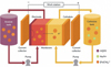 |
Fig. 1 Architecture of Redox-Active Electrode. |
3.1 Charging (oxidation at anode)
In the course of charging, a voltage from outside is imposed that enables the oxidation reactions to occur at the anode. The redox-active compound anthraquinone-2,6-disulfonate (AQDS2⁻) present in the anolyte gives up an electron at the interface of the electrode. This oxidation not only captures charge in the redox-active electrode but also heightens the electrochemical potential for ion movement. The mechanism is exemplified by the oxidation reaction:
 (1)
(1)
3.2 Electron transport
The anode's oxidation process leads to the release of electrons, which the applied voltage drives through the external circuit to the cathode. This electron movement counts as the electrical current in the system and links the anodic and cathodic redox reactions. The electrons are not moved through the electrolyte but rather through the conductive path only. This process is illustrated as follows:
 (2)
(2)
3.3 Ion transport through membrane
In order to keep the positive and negative charges equal during the transfer of electrons, the ions present in the electrolyte move to the side of the ion-exchange membrane opposite to where they were originally located. The ions that are the opposite to the electrons in the external circuit, namely sodium (Na⁺), hydrogen (H⁺), or nutrient ions, move through the membrane to neutralize the charge that has been separated. The membrane acts as a gate that opens for ions but closes for the bulk mixing of the two different solutions, anolyte and catholyte. The migration of ions can be depicted as follows:
 (3)
(3)
3.4 Discharging (reduction at cathode)
In the process of discharging, the arriving electrons at the cathode promote the reduction reactions of the catholyte redox species. Ferricyanide ions [Fe (CN)6]3− are de-electronised at the surface of the cathode and transformed into the corresponding ion, ferrocyanide [Fe(CN)6]4−. This reduction process allows the stored charge to be released and thus makes it possible for ions to be absorbed or released from the electrolyte. The reaction is depicted as follows:
 (4)
(4)
AQDS2⁻ and ferro/ferricyanide species enhance selective nitrogen and phosphorus recovery through reversible redox reactions and improved charge transfer. AQDS2⁻ supports electron storage and nutrient ion interaction, while ferro/ferricyanide facilitates stable electron transport and charge compensation. These redox-active materials improve selective ion adsorption and overall FCDI recovery efficiency.
4 Flow-electrode capacitive deionization (FCDI)
Flow-Electrode Capacitive Deionization (FCDI) is a novel electrochemical technology that purifies water by continuous ionic removal and recovery. This method makes use of slurries of conductive carbon particles as electrodes instead of the conventional fixed solid electrodes. The application of an external voltage results in the electrostatic and/or faradaic adsorption of dissolved ions onto the flow-electrode particle surfaces. The constant slurry circulation allows for continuous desalting and also avoids the saturation of the electrodes. The ions absorbed in actual processes can be liberated in a separate stream by changing applied voltage polarity, or operating conditions. This process of ion release facilitates the effective regeneration of electrodes without having to halt the operation. FCDI is especially appealing for the selective recovery of nutrients and for large-scale water treatment applications.
A Flow-Electrode Capacitive Deionization (FCDI) system utilizing individual cation and anion exchange membranes for the management of ion transport is depicted in Figure 2. Application of voltage causes the cations to move towards the negatively charged flow electrode and the anions to the positively charged one. Ion-exchange membranes are a barrier to ions of the same charge and permit the passage of ions with opposite charges only, thereby increasing the separation efficiency. Flow electrodes are continuously circulating carbon slurry, which prevents saturation and allows for stable operation. The removal of ions from the feed stream results in the generation of treated water at the outlet.
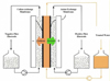 |
Fig. 2 Flow-Electrode Capacitive Deionization. |
4.1 Voltage application
Initially, an external power source applies a voltage across the flow electrodes, thus starting the FCDI process. The potential difference that has been applied charges the electrodes and creates an electric field across the cell. The electric field is the driving force for electrons to flow through the external circuit and for ions to migrate in the electrolyte. This situation can be described by the following equation:
 (5)
(5)
4.2 Ion migration
After the electric field is created, the ions that are dissociated react to the electrostatic force in the cell. The ions that are positively charged go to the electrode (cathode) that is negatively charged while the ions that are negatively charged go to the electrode (anode) that is positively charged. This process of ion migration causes a decrease in the ionic concentration of the feed stream. The migration process is shown as:
 (6)
(6)
4.3 Membrane transport
When ions move because of the electric field, ion‐exchange membranes manage their transport in such a way that there is no net charge build-up. The cation‐exchange membrane (CEM) gives pass only to the positively charged ions and opposes the ones that carry negative charge, meanwhile the anion‐exchange membrane (AEM) works vice versa. The process is such that leak of co‐ions is prevented and therefore separation efficiency is enhanced. The process is described as follows:
 (7)
(7)
The ion transport through the membrane is described by the Nernst-Planck equation:
 (8)
(8)
where ion flux is governed by diffusion and migration under an electric field. lon-exchange membranes enhance selectivity by allowing counter-ions while restricting co-ions, supporting efficient nitrogen and phosphorus separation in the FCDI system.
4.4 Ion adsorption
The ions that have successfully gone through the membranes now arrive at the flow electrodes where they get deposited on the surface of the suspended carbon particles. The deposition of the ions takes place via electrostatic attraction in the electric double layer and, if there are redox-active materials, also through faradaic reactions. This adsorption phase completely depletes the bulk solution of ions. The process is reversible and can be depicted as follows:
 (9)
(9)
The charge storage in FCDI involves both capacitive and faradaic contributions. Capacitive storage occurs via electrostatic ion adsorption, while faradaic processes involve reversible redox reactions of AQDS2⁻ and ferro/ferricyanide. The combination enhances charge utilization, reduces energy losses, and improves overall system efficiency.
5 Integrated experimental for redox-active flow-electrode capacitive deionization (FCDI) system
The Integrated Experimental Redox-Active FCDI System, a cutting-edge system, harnesses the power of flowable electrodes and ion-selective membranes to give the highest desalination efficiency possible. The electrode slurry is prepared and controlled very precisely to achieve the required conductivity and surface area. The FCDI cell will let the anode and cathode flows through alternately, thus making it possible for ion adsorption to take place through redox reactions. Ion exchange membranes are utilized to permit the selective ion transport while at the same time blocking the mixing of the electrodes. The feedwater is first treated to enhance its compatibility with the system and then to boost its performance. The post-process analysis comprises IC, UV, and ICP-OES techniques to evaluate the amount of ions removed and the presence of trace elements. The processing of the final product involves the determination of concentration factors and the making of purified output for recycling.
The purifying process of Flow Electrode Capacitive Deionization (FCDI) involves multiple stages, the first of which is the electrode preparation in the Electrode Lab. Here, synthesis, particle grading, and characterization are carried out and represented in Figure 3. The FCDI Cell Module is composed of a design where anode and cathode flows are divided by ion exchange membranes that enable the removal of the ions. The system's performance and ion concentrations are tracked by using analytical tools like IC, UV, and ICP-OES. The pre-treatment of feedwater occurs on the output side, while the purified product is subjected to concentration factor calculation and further processing.
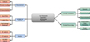 |
Fig. 3 Integration of Redox-Active Flow-Electrode Capacitive Deionization (FCDI) system. |
5.1 Electrode preparation
First, redox-active materials like quinone or polyaniline (PANI) are synthesized and then processed into particles of specific size so that they can be uniformly distributed and have the same electrochemical activity in the flow electrode slurry. The grading of the particles has a direct effect on the surface area and ion-accessible sites which determine the storage capacity of the electrode. The electrochemical characterization process (cyclic voltammetry for instance) measures the reversible redox behavior and the capacitance of the material that is effective. What rules this part is the basic interaction. The performance of PANI and quinone-based electrodes depends on their structural and surface properties. SEM is used to confirm morphology, XRD identifies material structure, and BET determines surface area and active sites. These characteristics improve ion accessibility and redox activity, thereby enhancing charge storage and ion recovery in FCDI systems.
 (10)
(10)
where the stored charge Q defines the theoretical ion capture capacity of the electrode under an applied voltage V and material capacitance C. Electrochemical characterization of the synthesized redox-active materials was performed using cyclic voltammetry to determine redox potentials, reversibility, and stability under operational conditions.
5.2 Feed pre-treatment
In the process of feed pre-treatment, coarse filtration is first done on raw water or wastewater to get rid of suspended solids that can not only block the flow channels in the FCDI cell but also foul the membranes. The integration of energy-efficient wastewater treatment strategies supports sustainable nutrient recovery from coastal and marine environments. This approach reduces energy consumption while maximizing recovery of valuable nitrogen and phosphorus species. Then, pH adjustment is done to ensure that ionic species are in forms that favor either electrostatic or redox-driven uptake (e.g., NH_4 ^+vs NH_3, PO_4 ^(3-) speciation). Ions are not eliminated in this process, rather, they are transferred between the different phases and hence, strict mass conservation is in force. The ion balance is denoted as
 (11)
(11)
ensuring that any reduction in effluent concentration is accounted for by ion capture or removal upstream. Equation (12) defines the recovery percentage of ions by comparing the amount recovered after FCDI treatment to the initial ion concentration in the feed solution.
 (12)
(12)
The mass balance validation is performed using recovery percentage calculations based on inlet and outlet ion concentrations. The recovery efficiency is defined as the ratio of recovered ions to the initial ions present in the feed solution. This calculation ensures that ion removal corresponds to actual recovery within the system, thereby confirming mass conservation and supporting the reliability of the feed pre-treatment assumptions in the FCDI process.
5.3 Flow electrode preparation
The solid fraction of the slurry is set by the flow electrode preparation process, during which the previously synthesized redox-active particles are mixed with a carrier electrolyte to form a stable slurry, typically with 5–30 wt% solids that are a trade-off between capacity and flowability. With continuous circulation, particles get uniformly distributed, and therefore, there are no sedimentation or aggregation issues that could eventually plug flow channels or affect negatively the electrochemical performance. The viscosity of the slurry must be managed very carefully; if it is too thick, the resistance to pumping will rise; on the other hand, if it is too thin, the capability of collecting ions will be lowered. The solid fraction of the slurry is defined by
 (13)
(13)
where ϕ is the weight percent of solids, msolid is the mass of redox-active particles, and melectrolyte is the mass of the carrier electrolyte? The rheological behavior of the flow-electrode slurry is important for the scalability and continuous operation of the FCDI system. Viscosity affects pumping efficiency and flow stability, where higher solid loading increases resistance while lower loading reduces ion capture ability. An optimal balance is required to ensure stable circulation without clogging and to support practical large-scale operation.
5.4 FCDI cell operation
During FCDI, the flow-electrode slurry which has been prepared is continuously pumped through the anode and cathode channels of the cell. The application of the external voltage causes the target ions in the feed water to move towards the electrodes where they are captured by the redox-active particles through electrostatic and faradaic interactions. The continuous recirculation of the slurry promotes mass transfer and keeps the ion transport stable and uniform throughout the system. The FCDI system was operated under controlled flow conditions with a feed flow rate of 50 mL/min and flow-electrode circulation rate of 100 mL/min to maintain stable ion transport and continuous desalination performance. Ion-exchange membranes were employed to improve selective ion migration between compartments. The flow electrode consisted of conductive carbon materials integrated with AQDS2⁻ and ferrocyanide redox-active species to enhance charge transfer and nutrient recovery efficiency.
The ion capture efficiency is influenced by the operating parameters such as applied voltage, current density, flow rate, membrane selectivity, and the redox potential of the electrode materials, and these conditions must be adjusted specifically for nitrogen and phosphorus species. The ion removal kinetics can be described by first-order kinetics as:
 (14)
(14)
where C is the ion concentration in the feed solution (molL−1) and k is the ion uptake rate constant (s−1).
5.5 Capture and release (polarity reversal)
The FCDI apparatus is reconfigured to a release mode by inverting the cell polarity or applying a suitable chemical stimulus after ion adsorption. This change frees the ion-electrode bonds, which results in the release of the already trapped nitrogen and phosphorus compounds into the more concentrated product stream. The ions that are disengaged are collected in the form of a concentrated solution for further processing or recycling. Accurate desorption is of utmost importance to reactivate the flow electrodes and to maintain the system's peak performance over the long term while the conditions must also be such as to prevent unwanted reactions such as water splitting. The criterion for measuring desorption efficacy is expressed as follows:
 (15)
(15)
where η is the percentage of captured ions successfully recovered, Cproduct and Vproduct are the concentration and volume of the recovered product, and Ccaptured and Vcaptured represent the total ions initially stored in the electrodes.
5.6 Product processing
Once the concentrated nitrogen and phosphorus solution is disposed of, it goes to the next stage of processing where resource recovery will take place. The nutrients in the solution form are changed into recoverable forms by means of chemical treatments such as struvite precipitation for phosphorus or ammonia stripping for nitrogen. This step not only raises the purity of the product but also renders it possible to use it practically as fertilizers or chemical feedstocks. The concentration factor, representing the extent of enrichment achieved, is employed to measure the product processing effectiveness. The concentration factor can be stated as follows:
 (16)
(16)
where Cproduct is the recovered ion concentration and Cfeed is the initial ion concentration in the feed solution.
5.7 Analysis and QA/QC
Finally, the analytical techniques such as ion chromatography (IC), UV-visible spectroscopy, and ICP-OES are employed to determine ion removal, recovery efficiency, and trace elements. Proper analyses will guarantee data validity and support the selectivity of nitrogen and phosphorus. The process's sustainability will be measured by the ratio of energy used to the amount of nutrients recovered, which will show the energy performance. Specific energy consumption will be so defined:
 (17)
(17)
where Especific is the energy required per gram of nutrient recovered (Whg−1), Wtotal is the total electrical energy consumed (Wh), and mN/P recovered is the mass of nitrogen or phosphorus recovered (g).
5.8 Electrochemical characterization and stability analysis
Cyclic voltammetry (CV) was conducted to assess the electrochemical behavior and stability of AQDS2⁻ and the ferri/ferrocyanide redox couple within a controlled potential window to avoid water electrolysis. Both systems exhibited well-defined and symmetric redox peaks with minimal peak separation, indicating high reversibility and efficient electron transfer. The stable peak responses over repeated cycles confirm strong thermodynamic stability and resistance to degradation. The operating voltage was maintained below 1.23 V, ensuring safe and energy-efficient operation. These results validate the suitability of the redox couples for stable and continuous FCDI performance.
6 Results and discussion
The cyclic voltammetry results confirm the electrochemical feasibility of the system, showing distinct and stable redox peaks for AQDS2⁻ and ferro/ferricyanide, which indicate efficient and reversible charge transfer. The minimal peak separation and consistent response across cycles demonstrate low resistance and strong thermodynamic stability, supporting continuous FCDI operation with reduced energy losses.
6.1 Effect of applied voltage on FCDI
The performance of FCDI concerning ASRR and the increase of energy consumption, are the effects of the applied voltage. The voltage reaches a peak of about 1.2 V, after which the ASRR and energy consumption decline, thus revealing an optimal operating point as depicted in Figure 4. On the contrary, energy consumption increases uninterruptedly with the rise of the applied voltage. This situation uncovers a compromise that the higher voltage enhances the removal rate up to a certain point but with the price of using more energy.
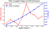 |
Fig. 4 Applied voltage on FCDI. |
6.2 Effect of carbon content on FCDI performance
The group of diagrams illustrates the effect of changing carbon content on important FCDI performance metrics. ASRR along with carbon loading, indicates an optimal range rather than a linear trend that is displayed in Figure 5. Current efficiency nearly stays the same, which implies that there is an even charge exploitation over the different contents. Energy consumption keeps on growing steadily as more carbon is incorporated because of increased resistance and mass. Thermodynamic energy efficiency (TEE) drops, which points to the diminishing returns at high carbon loadings. The influence of carbon loading on FCDI performance is related to pore structure and electrical conductivity. Increased carbon content improves conductive pathways and ion adsorption, while excessive loading may increase internal resistance and reduce material efficiency.
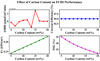 |
Fig. 5 Carbon content on FCDI performance. |
6.3 FCDI system performance radar chart
The radar chart gives a summary of total FCDI system efficiency among five indicators. Water recovery and current efficiency are at the top with high values, which means strong separation capability is seen in Figure 6. TEE also remains quite high, which indicates good energy utilization. Both productivity and ASRR are moderate, meaning there is still a room for operational improvement. In general, the chart presents an even and good FCDI performance.
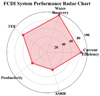 |
Fig. 6 System performance radar chart. |
6.4 FCDI vs other desalination technologies
The comparison underlines the technologies CDI, MCDI, ED, and RO with a focus on FCDI. FCDI demonstrates lower energy consumption and higher nutrient recovery efficiency compared to CDI, MCDI, electrodialysis, and reverse osmosis under similar operating conditions.
The least energy consumption is depicted in Figure 7, among the compared methods, FCDI being the one with the least energy consumption. The water recovery of FCDI is remarkably higher and almost reaches total recovery. Conventional methods require more energy and have lower recovery rates. The graph illustrates the superior efficiency and sustainability of FCDI. A comparative analysis of water treatment technologies shows that adsorption suffers from poor regeneration, while electrodialysis (ED) and reverse osmosis (RO) are energy-intensive for dilute streams. Capacitive deionization (CDI) improves energy efficiency but is limited by electrode saturation and selectivity, and membrane CDI (MCDI) enhances selectivity but faces membrane fouling and stability issues. In contrast, the proposed redox-active FCDI system enables continuous operation, improved ion selectivity, and lower energy consumption, making it more suitable for efficient and sustainable nutrient recovery.
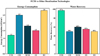 |
Fig. 7 Desalination technologies. |
6.5 Current profile during FCDI operation
The current fluctuation throughout the FCDI operation period is depicted in this graph. As the ions are taken away from the feed solution, the current gradually goes down. This decline shows the reduction in ionic conductivity and is depicted in Figure 8 together with the desalination development. The smooth profile indicates the stable and controlled behavior of the system. Such behavior is typically exhibited by capacitive-based desalination processes.
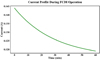 |
Fig. 8 Current profile during FCDI operation. |
6.6 FCDI desalination performance over time
The graph shows the effluent's salt concentration throughout the processing time. The quick drop of salt concentration from the feed value towards zero almost completely is represented in Figure 9. This kind of behavior suggests the swift and proficient FCDI deionization process. The low concentration continues to be seen for the entire period. The result is a confirmation of the very high efficiency of desalination during long operation.
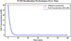 |
Fig. 9 Desalination performance over time. |
6.7 Effect of feed concentration on FCDI performance
This graph shows how feed salinity influences concentration reduction and removal efficiency. As seen in Figure 10, the absolute concentration reduction goes up along with the feed concentration. On the other hand, the removal efficiency decreases at higher salinities. This means that apart from the physical limitations faced when working with high ionic strengths, there is also a limit to the electrodes’ capacity. Such a trend stresses the need for saline feeds to be customarily operated at conditions that would yield highest efficiency.
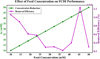 |
Fig. 10 Feed concentration on FCDI performance. |
6.8 Baseline FCDI simulation performance summary
The basic simulation of Flow Electrode Capacitive Deionization (FCDI) demonstrates a remarkable water recovery of 97% along with an even better productivity rate of 90 L/m2/h, which indicates efficient processing as depicted in Figure 11. The current efficiency is also quite high at 85% with 30 mM concentration reduction, which means ions are being removed effectively. Energy consumption is relatively low at 0.170 kWh/m3, but still the thermodynamic energy efficiency is low at 29.38% which implies that optimization is needed. The ENRS value of 48.962 μmol/J indicates outstanding energy-normalized separation performance for desalination processes.
In practical wastewater treatment, ENRS quantifies the amount of nitrogen and phosphorus removed per unit of electrical energy, directly indicating the cost-effectiveness of nutrient recovery. TEE reflects how efficiently the supplied electrical energy is converted into useful ion separation work, providing a thermodynamic benchmark for minimizing operational losses. Together, these metrics demonstrate that the proposed FCDI system can achieve high nutrient recovery with low energy demand, supporting economically viable and sustainable full-scale wastewater treatment applications.
 |
Fig. 11 FCDI simulation performance summary. |
6.9 Optimized FCDI performance overview
The optimization of FCDI performance was carried out by varying operational parameters such as applied voltage and carbon loading while evaluating performance metrics including ASRR, ENRS, TEE, and energy consumption. The optimal operating condition was selected based on achieving high ion removal efficiency with minimum energy consumption and stable system operation. This optimization approach provides consistency and transparency in the evaluation of FCDI performance. The FCDI system optimized Key Performance Indicators are based on the baseline metrics where current efficiency (85%) and water recovery (97%) confirm the stable electrochemical and hydraulic performance, as represented in Figure 12. Energy consumption is at the very low level of 0.170 kWh/m3 and thermodynamic energy efficiency (TEE) undergoes a slight rise to 29.4% meaning that there is very little gain in energy utilization. The ENRS value goes up to 49.0 μmol/J implying that ion separation per unit energy has improved. All these findings indicate a highly developed system with a stable desalination throughput and an energy saving operation.
 |
Fig. 12 Optimized FCDI performance overview. |
6.10 Impact of carbon loading and voltage on FCDI performance
The performance of the FCDI system was evaluated under different carbon loadings and voltages, Table 1 presenting the comparison of performance metrics such as constant ASRR, current efficiency, productivity, water recovery, and concentration reduction. When the carbon loading is varied from 5% to 20%, the energy consumption (Ev) increases from 0.142 to 0.227 kWh/m3, while ENRS and TEE decrease, signifying the lowering of energy efficiency. The effect of voltage on the performance shows that while a low voltage of 0.8 V yields the maximum ENRS (110.16 mmol/J), the highest TEE (40%) and ASRR are achieved at 1.2 V, although the energy consumption increases compared to 0.8 V. On the other hand, a high voltage of 1.5V will greatly increase the energy consumption (0.266 kWh/m3) and thus will lower the efficiency metrics. These patterns can be seen as the illustration of the balance between the different operational settings and the energy-performance optimization in FCDI systems.
The performance metrics of the FCDI system were further evaluated using variance analysis for different carbon loading and applied voltage conditions. The observed variation in energy consumption, ENRS, and TEE indicates that voltage has a stronger influence on system efficiency, while carbon loading affects conductivity and ion transport behavior. The variance analysis supports the reliability and consistency of the reported FCDI performance trends.
Figure 13 presents the calibration relationship between ion concentration and detector response obtained using ion chromatography (IC) for accurate nutrient quantification.
Figure 14 illustrates the UV–Vi’s calibration curve used to determine nutrient concentration based on absorbance response under controlled conditions.
Figure 15 shows the ICP–OES calibration analysis used for precise elemental concentration measurement and trace metal validation in the FCDI system.
Figure 16 compares the detection limits of the analytical instruments employed for nutrient and elemental analysis during FCDI evaluation.
Table 2 summarizes calibration performance, detection limits, and quality assurance parameters of IC, UV–Vis, and ICP–OES measurements used in the study.
Carbon loading and voltage on FCDI performance.
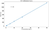 |
Fig. 13 IC calibration curve for ion concentration analysis. |
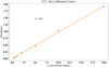 |
Fig. 14 UV–Vis calibration analysis for nutrient detection. |
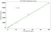 |
Fig. 15 ICP–OES calibration curve for elemental measurement. |
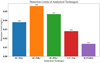 |
Fig. 16 Detection limits of IC, UV–Vis, and ICP–OES measurements. |
QA/QC validation and analytical performance.
7 Conclusion and future scope
The present investigation introduced a redox-active flow-electrode capacitive deionization (FCDI) system for the selective extraction of nitrogen and phosphorus from wastewater with better energy efficiency and operational reliability. The excellent performance of the unit in terms of desalination and nutrient recovery was established, as reflected in an incredible 97% water recovery, 85% current efficiency, and 90 L m⁻2 h⁻¹ productivity, thus approaching and confirming continuous and stable operation. For a concentration reduction of 30 mM, the unit consumed only 0.170 kWh m⁻3, which is a remarkable feature of the suggested framework, as it indicates that the whole process is very energy efficient. Besides, the improved FCDI system accomplished an energy-normalized removal score (ENRS) of about 49.0 μmol J⁻¹ and a thermodynamic energy efficiency (TEE) of 29.4%, indicating that the system was very effective in utilizing the electrical input and had a better ion separation capability. This indicates that the combination of redox-active electrodes with flow-electrode structure has increased selectivity, decreased electrode saturation, and supported the recovery of nutrients that is sustainable and besides, pilot-scale studies will be done to evaluate the feasibility of scaling up and the toughness of operations. Moreover, the recovery of nutrients will be packaged for downstream processes like struvite precipitation and ammonium through the integration of recovered nutrients.
Funding
This research received no external funding.
Conflicts of interest
The authors declare that they have no conflicts of interest related to this work.
Data availability statement
The data supporting the findings of this study are available from the corresponding author upon reasonable request.
Author contribution statement
Xihan Wang: Conceptualization, methodology, investigation, data analysis, writing – original draft.
Yanping Chen: Experimental investigation, data curation, validation.
Xinya Zhao: Formal analysis, visualization, writing – review and editing.
Xiujun Tian: Supervision, project administration, conceptual guidance, writing – review and editing.
All authors have read and approved the final manuscript.
References
- K. Biju, J. Brema, Water quality degradation and eutrophication risk in the Ashtamudi wetland: role of physicochemical factors and microplastics, Environ. Monit. Assess 197, 1389 (2025) [Google Scholar]
- C. Marques, S. Güneş, A. Vilela, R. Gomes, Life-cycle assessment in agri-food systems and the wine industry—a circular economy perspective, Foods 14, 1553 (2025) [Google Scholar]
- J. Shamshad, R.U. Rehman, Innovative approaches to sustainable wastewater treatment: a comprehensive exploration of conventional and emerging technologies, Environ. Sci. Adv. 4, 189–222 (2025) [Google Scholar]
- J. Park, J. Lee, I.T. Shim et al., Electrochemical direct lithium extraction: a review of electrodialysis and capacitive deionization technologies, Resources 14, 27 (2025) [Google Scholar]
- Z. Gao, L. Wang, X. Huang et al., Selective single-atom adsorption for precision separation of lead ions in tap water via capacitive deionization, Water Res. 268, 122665 (2025) [Google Scholar]
- R. Akbarzadeh, M. Ernst, R. Meißner, B. Fiedler, Capacitive deionisation for water desalination review: experimental and simulation, Sci. Technol. Adv. Mater. 26, 2546286 (2025) [Google Scholar]
- H.M. Saif, J.G. Crespo, S. Pawlowski, How should flow electrode capacitive deionization (FCDI) be operated to achieve efficient desalination and scalability? Desalination 606, 118769 (2025) [Google Scholar]
- T. Shahzad, S. Nawaz, H. Jamal, T. Shahzad, F. Akhtar, U. Kamran, A review on cutting-edge three-dimensional graphene-based composite materials: redefining wastewater remediation for a cleaner and sustainable world, J. Compos. Sci. 9, 18 (2025) [Google Scholar]
- A. Allende, A. Alvarez-Ordóñez et al., Microbiological hazards associated with the use of water in the post-harvest handling and processing operations of fresh and frozen fruits, vegetables and herbs (ffFVH): Part 2 – A dynamic mass balance model for handling and processing operations in ffFVH using water, EFSA J. 23, e9173 (2025) [Google Scholar]
- L. Valverde-Vozmediano, E. Martínez-Sabater, M.M. Jordán et al., Sustainable phosphorus and protein recovery from different organic wastes: process optimization and struvite precipitation potential, Agronomy 15, 2305 (2025) [Google Scholar]
- Q. Tran, J.J. Oak, J. Kim, X. Jin, Enhancing nutrient water recovery: an integrated electrodialysis–forward osmosis approach for reduced energy consumption and membrane fouling, Sep. Purif. Technol. 357, 130164 (2025) [Google Scholar]
- C.G. Jinitha, P. Abisha, S. Sonia, G. Bharath, A critical review of activated carbon for CDI electrodes, emphasizing its biomass and commercial sources, activation methods, performance analysis, and future advancements, Biomass Convers Biorefin. 15, 16273–16306 (2025) [Google Scholar]
- Y. He, T. Gao, A. Gong, G. Wang, W. Si, P. Liang, Enhanced phosphate recovery in R-MCDI systems: synergistic effects of modified electrodes and membrane-electrode-current collector assembly, Water Res. 278, 123392 (2025) [Google Scholar]
- C. Oh, H.J. Oh, S. Yeon, B. Lee, J. An, Comparative analysis of MCDI and circulation-MCDI performance under symmetric and asymmetric cycle modes at pilot scale, Sustainability 17, 9744 (2025) [Google Scholar]
- M. van der Wal, R. Rovai, K. Nijmeijer, Z. Borneman, Bipolar membrane electrodialysis enhanced nutrient separation in manure treatment, Environ. Technol. Innov. 39, 104326 (2025) [Google Scholar]
- C.J. Pan, S.C. Lin, B.J. Hwang, W.H. Huang, C.I. Lee, Stable Zn metal deposition/stripping in Zn-Li dual-ion batteries achieved by acetonitrile-water co-solvent enhanced acetamide-based deep eutectic electrolytes, Future Batteries 7, 100108 (2025) [Google Scholar]
- X. Foster, W.A. Tarpeh, H. Dong, C. Vaneeckhaute, Enhancing the regeneration efficiency of a hybrid anion exchange resin for removal of phosphorus from wastewater with a lower environmental impact, J. Water Process. Eng. 69, 106851 (2025) [Google Scholar]
- S.C. Motshekga, Nutrient recovery from wastewater using bioelectrochemical systems: a review on nitrogen and phosphorus removal, J. Water Process. Eng. 79, 109031 (2025) [Google Scholar]
- Q. Wei, C. Cui, Z. Wang et al., Enhanced phosphate removal and recovery from wastewater by flow-electrode capacitive deionization (FCDI): role of [Fe(CN)6]3−/4− redox couple, Water Res. 277, 123304 (2025) [Google Scholar]
- F. Xu, L. Yuan, R. Zhao et al., Selective ion separation by capacitive deionization: a comprehensive review, Materials 18, 1107 (2025) [Google Scholar]
- M. Liu, M. He, J. Han et al., Recent advances in capacitive deionization: research progress and application prospects, Sustainability 14, 14429 (2022) [Google Scholar]
- S. Kumar, N.M. Aldaqqa, E. Alhseinat, D. Shetty, Electrode materials for desalination of water via capacitive deionization, Angew. Chem. 135, e202302180 (2023) [Google Scholar]
- A.A. Oladipo, M. Ahmad, Energy-efficient ion recovery from water using electro-driven membranes: a comprehensive critical review, Water 17, 2456 (2025) [Google Scholar]
- M. Li, Z. Ma, T. Zhang, W. Wang, L. Xue, D. Zhu, Boron/nitrogen co-doped reticulated porous carbon frameworks encapsulating cobalt selenide: An advanced nanomaterial for ultrasensitive simultaneous detection of xanthine and uric acid in human serum, Microchem. J. 218, 115188 (2025) [Google Scholar]
- C. Tewari, K.S. Rawat, S. Yoon, Y.C. Jung, Polymer-based electrolytes for organic batteries, Energies 18, 5168 (2025) [Google Scholar]
- M.H. Sadr, A. Pashazadeh, Metal-organic frameworks based on functionalized polydentate heteroatom linkers integrated by graphitic carbon nitride nanosheets on epoxy–graphite electrodes: application in electrocatalytic determination of propranolol, Sens. Biosens. Res. 50, 100913 (2025) [Google Scholar]
- Ş.F. Küçükayar, Ş. Kaya, V. Şimşek, M.O. Caglayan, Z. Üstündağ, S. Şahin, Carbonised Typha tassel-modified enzymatic electrodes for ferrocene-mediated glucose biosensor and glucose/air biofuel cell applications, Microchem. J. 208, 112213 (2025) [Google Scholar]
- R. Ghamarpoor, B. Ramezanzadeh, A multifunctional hybrid MXene/ZIF/semiconductor-based coating for photocatalytic degradation and long-term marine corrosion protection, Adv. Ind. Eng. Polym. Res. (2025). https://doi.org/10.1016/j.aiepr.2025.09.010 [Google Scholar]
- S. Kasiński, P. Kowal, K. Czerwionka, Advanced technologies for nitrogen removal and recovery from municipal and industrial wastewater, Materials 18, 1422 (2025) [Google Scholar]
- M. Zielińska, K. Bułkowska, Use of membrane techniques for removal and recovery of nutrients from liquid fraction of anaerobic digestate, Membranes 15, 45 (2025) [Google Scholar]
- S. Zhang, P. Wang, W. Xue et al., Symmetric anion exchange membranes enhance arsenic removal and overcome conductivity limitations in FCDI systems, NPJ Clean. Water 8, 70 (2025) [Google Scholar]
Cite this article as: Xihan Wang, Yanping Chen, Xinya Zhao, Xiujun Tian, Redox-active electrode architectures for selective nitrogen and phosphorus recovery via flow-electrode capacitive deionization (FCDI): a material-driven strategy, Int. J. Metrol. Qual. Eng. 17, 13 (2026), https://doi.org/10.1051/ijmqe/2026010
All Tables
All Figures
|
Fig. 1 Architecture of Redox-Active Electrode. |
| In the text | |
|
Fig. 2 Flow-Electrode Capacitive Deionization. |
| In the text | |
|
Fig. 3 Integration of Redox-Active Flow-Electrode Capacitive Deionization (FCDI) system. |
| In the text | |
|
Fig. 4 Applied voltage on FCDI. |
| In the text | |
|
Fig. 5 Carbon content on FCDI performance. |
| In the text | |
|
Fig. 6 System performance radar chart. |
| In the text | |
|
Fig. 7 Desalination technologies. |
| In the text | |
|
Fig. 8 Current profile during FCDI operation. |
| In the text | |
|
Fig. 9 Desalination performance over time. |
| In the text | |
|
Fig. 10 Feed concentration on FCDI performance. |
| In the text | |
|
Fig. 11 FCDI simulation performance summary. |
| In the text | |
|
Fig. 12 Optimized FCDI performance overview. |
| In the text | |
|
Fig. 13 IC calibration curve for ion concentration analysis. |
| In the text | |
|
Fig. 14 UV–Vis calibration analysis for nutrient detection. |
| In the text | |
|
Fig. 15 ICP–OES calibration curve for elemental measurement. |
| In the text | |
|
Fig. 16 Detection limits of IC, UV–Vis, and ICP–OES measurements. |
| In the text | |
Current usage metrics show cumulative count of Article Views (full-text article views including HTML views, PDF and ePub downloads, according to the available data) and Abstracts Views on Vision4Press platform.
Data correspond to usage on the plateform after 2015. The current usage metrics is available 48-96 hours after online publication and is updated daily on week days.
Initial download of the metrics may take a while.