| Issue |
Int. J. Metrol. Qual. Eng.
Volume 17, 2026
Topical Issue - MAIQS 2025
|
|
|---|---|---|
| Article Number | 2 | |
| Number of page(s) | 10 | |
| DOI | https://doi.org/10.1051/ijmqe/2025011 | |
| Published online | 09 January 2026 | |
Research Article
Design and implementation of robot-assisted systems for non-destructive testing
1
School of Mechanical and Materials Engineering, North China University of Technology, Beijing 100144, PR China
2
Department of Mechanical and Aerospace Engineering, Brunel University London, Uxbridge UB8 3PH, UK
* Corresponding author: This email address is being protected from spambots. You need JavaScript enabled to view it.
Received:
28
October
2025
Accepted:
10
November
2025
Abstract
With wide application of new materials, structures, and technologies in modern industry, testing objects were no longer limited to conventional materials and common shapes. Demands of testing new materials and complex shapes bring challenges to researchers in non-destructive testing area. Combining robots, which have been widely used in industry, with the non-destructive testing technology can replace manual operation and improve testing precision. Additionally, the robot-assisted systems can enhance efficiency and safety of the testing process. The researchers have carried out numerous designs and implementations to combine robots with non-destructive testing devices. This article presents four non-destructive testing systems with robot, including single-arm robot holding a transducer, single-arm robot holding a tested part, and twin-arm robot holding two transducers. In conclusion, application scopes are analyzed to help users select appropriate systems according to sizes, materials and defect types.
Key words: Robot / ultrasonic testing / non-destructive testing / testing system / curved surface
© H. Zhang et al., Published by EDP Sciences, 2026
 This is an Open Access article distributed under the terms of the Creative Commons Attribution License (https://creativecommons.org/licenses/by/4.0), which permits unrestricted use, distribution, and reproduction in any medium, provided the original work is properly cited.
1 Introduction
With development of robot technology, industrial robots have been widely used in various fields such as welding, palletizing, assembly, spraying, polishing, loading and unloading. Various robot-assisted systems are designed according to application requirements. The robots can perform specific operations automatically according to preset programs, therefore replacing manual labors for some arduous, complex and dangerous tasks. Non-destructive testing (NDT), as a widely used testing technology in industry, is an important way to ensure manufacturing quality and reliability. It has been widely used in various fields such as aviation, aerospace, shipping and petrochemicals. NDT's greatest advantages lies in its non-destructive natures based on certain physical principles. Nowadays, automated testing systems that combines robots with NDT technologies are gradually moving from laboratories to factories.
Machine parts in modern design is increasingly trending towards curved shapes to meet the requirements of fluid dynamics, space utilization, and aesthetics. However, the curved shapes not only bring new difficulties to manufacturing, but also present new challenges to test defects. The NDT methods which not contact with surface are suitable to test curved surfaces, and are currently a hot spot. Combining robot with NDT can fully leverage the robot's advantages of flexible spatial movement and positioning ability, thereby enable automated testing of complex curved surfaces. For example, combining robot with ultrasonic or eddy current can be applied to test aircraft engine blades. Combining robot with radiation or laser can prevent operators exposing in dangerous environments.
Common robot-assisted systems for NDT are divided into two modes, including single-arm robot (SAR) mode and dual-arm robot (DAR) mode. The SAR mode can be further divided into two types, which is single-arm robot holding transducer and single-arm robot holding tested part. In Addition, muti-robots mode that containing more than two robots in a system is also widely used to test parts. In this research, we mainly describe the SAR mode and the DAR mode, which have covered most of the applications.
2 Single-arm robot holding transducer
In the NDT area, the application of the SAR mode is more common than that of DAR mode. Among them, there are both customized robot designed for special requirements and 6 degree of freedom (DOF) robot for common requirements. In the process of aircraft manufacturing, research on the NDT of curved parts has been carried out for a long time due to strict quality control. Isawa [1] installed superconducting quantum interference device (SQUID) on end-effect of a 6 DOF robot. The presented SQUID system can be used to test ferromagnetism generated by martensitic phase transition or austenitic phase transition in stainless steel. To replace human operator with robot, Ji [2] designed and fabricated a new set of ultrasonic probe adapters and sample holding fixtures for fully automated robotic inspection. Meng [3] established a terahertz time-domain spectroscopy (THz-TDS) system combing robot arm and terahertz device, some efforts to improve accuracy of thickness measurement by terahertz time-of-flight imaging method is proposed. Wang [4] proposed an automatic water immersion ultrasonic C-scan testing technology based on a six-axis robot to detect debonding defects on joint interface of divertor. Research and development ideas, principles and control logic of the testing system are explained in the article. Choi [5] designed and fabricated an automated inspection robot to detect defects in offshore wind turbine material. Experiment results demonstrated that the robot was capable of detecting any defects within the area of 25000 mm2. In addition, some mobile robots were designed to fit specific environments. For example, Toman [6] presented the design and testing of a universal mobile platform with interchangeable sensing systems for non-destructive inspection of aircraft structures with various angles of inclination. Ayala [7] shown design, construction, and control of a climbing robot prototype inspired by geckos for NDT tasks set in high or narrow environments. The presented robot can scale smooth surfaces with an inclination of up to 90° without leaving a mark or damaging surface. Wickramanayake [8] reported an innovative development of in-pipe robotic sensing suite leveraging ultrasonic sensing to inspect thickness of spray linings. Extensive lab tests demonstrated that measurement accuracy reached to sub-millimeter.
Among various robot-assisted NDT systems, the 6 DOF robot is the most widely used type. It moves flexibly in working space; therefore, it is suitable to test parts with complex surfaces such as engine blades, car wheels, bearings and gears.
2.1 Configuration of the testing system
The testing system of single-arm robot holding transducer is shown in Figure 1, which includes a servo control module, a testing device, a 6 DOF robot, an industrial computer and a fixture. The servo control module is consisted of a programmable muti-axis controller (Turbo PMAC Clipper) from Delta Tau company in the US and a robot servo controller (YR-MH00006-A00) from Yaskawa company in the Japan. The PMAC is featured with open-source and flexible programmability, therefore it is suitable for secondary development. Different testing devices can be installed in the system according to the test requirements. Taking ultrasonic testing as an example, the testing device is consistent of an ultrasonic transducer installed on the end-effector of the robot and a signal transceiver card installed in the computer. The signal transceiver card transmits drive pulse and receives echo signal according to preset parameters. Piezoelectric crystal in the transducer converts the drive pulse into high-frequency vibration, and then the vibration spread outward as ultrasound. The 6 DOF robot as an actuator of the testing system is used to move and scan over the surface of the tested part. The industrial computer is a control core of the testing system to gather position data from servo control module and wave signal from testing device. Finally, a C-scan image of the tested area is displayed in real time to locate positions of defects.
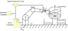 |
Fig. 1 Configuration of the mode that single-arm robot holds the transducer. |
2.2 Method to plan the scan trajectory
Before scanning over the surface of a part, it is necessary to plan scan trajectory. All parts in the testing system are regarded as rigid bodies and the relationship between certain two bodies is described in form of matrix combining both position and pose. For example, coordinate system {A} and coordinate system {O} are established on two bodies, then the position relationship of the two bodies is expressed as:
 (1)
(1)
The pose relationship of the two bodies is cosine calculation between unit vector xA, yA, zA of coordinate system {A} and unit vector xO, yO, zO of coordinate system {O}. It is expressed as:
 (2)
(2)
Finally, the relationship of the two bodies in the space is a combination of the equation (1) and the equation (2), and it is expressed as:
 (3)
(3)
Fixed X-Y-Z coordinate system method is introduced to simplify the equation (3) as:
 (4)
(4)
In Figure 1, the transducer is installed on the end-effector of the robot and the tested part is fixed on the turn table. Coordinate system {o} is established on the base of the robot as base coordinate. Coordinate system {e} is established on the end-effector of the robot, coordinate system {t} is established on the transducer of the robot, coordinate system {b} is established on the center of the tested part, coordinate system {w} is established on certain point w of the tested part.
In scan process of the single-arm robot holding transducer, it is necessary to keep a constant distance between the transducer and the tested points, and make the axis of the transducer in line with the normal direction of the tested surface. It means that the coordinate system of tested point {w} and transducer {t} must maintain a fixed position and pose relationship, and it is noted in matrix as  . The position and pose relationship between tested point {w} and workpiece coordinate system {b} is noted in matrix as
  . The scan points relative to the workpiece coordinate system {b} are generated based on 3D model using a computer-aided manufacturing (CAM) software with preset step value and feed value before the scan process. To maintain the transducer scan over the tested part with constant distance and orientation, it is necessary to transform the scan points into the transducer's scan trajectory base on the equation (5).
 (5)
(5)
During the scan process, the transducer scan along the tested points in the trajectory and receive the signals. Both the tested part and the robot are fixed and their relationship in space is noted as  , so the trajectory of the transducer relative to workpiece coordinate system {b} is transform into the base coordinate system {o} according to the equation (6), which makes it more convenient to control the robot.
 (6)
(6)
2.3 Implementation examples of the testing system
Wheel hub is main load-bearing component of vehicle, which related to traffic security. In manufacturing process, it not only pay attention to external quality, such as accuracy and surface roughness. But also focus on internal quality, like pores, sand holes, shrinkage cavities, shrinkage porosity and residual stress. The wheel hubs are large in size and heavy in weight, and their surface are complex. Therefore, it is suitable to be tested by the testing system of single-arm robot holding transducer, as shown in Figure 2. Water-jet coupling ultrasonic transducer is installed on the end of the 6 DOF robot and moves over the surface of the wheel hub to detect inner defects.
Due to the limitation of testing resolution, the ultrasonic testing can only detect internal defects. For surface cracks caused by residual stress, fatigue, and uneven temperature in casting, the eddy current transducer as shown in Figure 3 is a suitable choice.
The single-arm robot holding ultrasonic transducer can also be used to test residual stress in surface. Figure 4a is a sample containing weld heat-affect zone and Figure 4b is a cloud chart showing the distribution of the residual stress in the sample, which is detected by the testing system. Stress values in red areas are higher than those in blue area. The dark blue area at bottom represents that it has not been tested. It is obviously that the residual stress in the weld area is higher than that in other area. The width of red area in cloud chart shown in Figure 4b is consistent with the width of the weld heat-affected zone in the sample shown in Figure 4a.
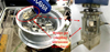 |
Fig. 2 Ultrasonic transducer to detect inner defects in wheel hub. |
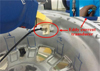 |
Fig. 3 Eddy current transducer to detect surface cracks on wheel hub. |
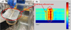 |
Fig. 4 Ultrasonic transducer to detect residual stress distribution. |
3 Single-arm robot holding tested part
For tested parts with small sizes and complex shapes such as blades, bearings and bolts, the non-destructive testing method based on the principles of ultrasonic, electromagnetic, infrared spectroscopy and radiation are used. Chakrapani [9] presented a field implementable ultrasonic scanning system. The common discontinuities in large wind turbine blades were tested using the laboratory-based system for proof of concept. Sinha [10] from Missouri University of Science and Technology Reactor (MSTR) developed a novel neutron/X-ray combined computed tomography (NXCT) system for non-destructive analysis. The successful operation demonstrated that it is useful for concealed material detection, material characterization, investigation of complex geometries and real imaging for in-situ studies. To extend the application of ECPT for NDT of non-conductive materials, Liu [11] proposed a method named eddy current pulsed thermography with an inductive heating layer (ECPT-IHL). The feasibility of ECPT-IHL was verified by conducting experiments on glass fiber-reinforced polymer (GFRP) specimens with flat-bottom back-drilled hole (FBH) defects. The results shown that ECPT-IHL is effective in detecting minor defects in GFRP laminates. Zheng [12] developed an advanced automatic inspection system (AAIS). The system can automatically detect, measure and classify discontinuities from the fluorescent penetrant inspection (FPI) images of aircraft parts. The result demonstrates that the system has significantly improved the efficiency of FPI with satisfactory accuracy. As a concept of deploying in situ thermography NDT, Avdelidis [13] presented an autonomous, novel and lightweight muti-axis scanning system with the intention of developing maximization of the blade area coverage in a single run with the utilization of the minimum number of system degrees of freedom and the maximum repeatability, as well as positional accuracy. Ley's [14] work dealt with the NDT of different composite parts and structures using line scanning thermography (LST). The LST technique is a quick and efficient methodology to scan wide areas and it has been used on the inspection of composite propellers, sandwich panels, motor case tubes and wind turbine blades.
Reviewing the latest researches, a common problem on the NDT lies in the fact that most of the high-precision devices based on novel technology have the characteristics of large size and heavy weight. The configuration of the single-arm robot holding tested part is a suitable choice to improve test precision for small size objects. Xiao [15] investigated an efficient scheme for ultrasonic test in which the tested object was grasped by a 6 DOF robot to maintain normal incidence of the sound beam to the surface, and pulse echo method is used to identify the flaw. The solution is suitable for the high-speed automatic inspection of complex structures. Maciejewski [16] describes a setup for NDT of composite combat helmets using terahertz time domain spectroscope (TDS) imaging and an industrial robot arm. The obtained results confirmed the capability of effectively detecting defects with a diameter exceeding 0.5 cm2. Ma [17] proposed an ultrasonic inspection system with a 6 DOF robot holding the aero-engine blade to measure the thickness. Pulse-echo laser ultrasonic testing (LUT) is used to inspect subsurface damages in composite materials. Ma [18] studied the use of 3D scan-generated models to generate the scan grids for controlling the robot arm's movement. A feasible design and implementation of the single-arm robot holding tested part for the NDT is presented in his research.
3.1 Configuration of the testing system
The testing system of single-arm robot holding tested part is suitable to test small-sized objects with complex surface. Taking aero-engine blade as an example, a prototype of the NDT system is shown in Figure 5. The system integrates hardware including a robot arm, a control cabinet and an ultrasonic probe, as well as software for robot controlling and test result imaging to present defects and thickness of the tested parts. The repetitive positioning accuracy of the robot arm is 0.08 mm to ensure a high positioning accuracy. The pulse-echo wave are displayed in real time during the scanning process, which is called A-scan image. Each frame of the image is corresponded with the scan points in the trajectory. These images are displayed continuously during the scan process, therefore forming the real-time image. Peak values of the wave are extracted and transformed into grayscale values under certain scale. The grayscale values are corresponded with the scan points in trajectory forming another image, which is called C-scan image. The defects and the thickness of the tested parts are shown on the C-scan image for further automated recognition and elimination.
The configuration of the system is shown in Figure 6. It mainly consists of three components, including a robot control system, an ultrasonic testing system and an auxiliary system. An industrial computer is used for overall coordination of the three components. The ultrasonic testing system includes an ultrasonic transceiver device and an analog-to-digital (A/D) conversion card in the industrial computer to collect the pulse echo signals reflected by the tested part. The challenge lies in the fact that the ultrasonic transceiver device needs to be triggered precisely during the robot's high-speed movement. A field programmable gate array (FPGA) card with large storage and high-speed reading/writing (R/W) capabilities is developed to match the pulse echo signals with the scan points accurately. Therefor the impact of matching errors on defect location is reduced.
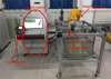 |
Fig. 5 A prototype of single-arm robot holding tested part. |
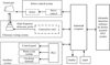 |
Fig. 6 Configuration of the mode that single-arm robot holds the tested part. |
3.2 Implementation examples of the testing system
Blades are typical components with complex surface. An imitation of blade as shown in Figure 7a is designed and manufactured to verify the performance of the testing system. There are five artificial defects on the surface of the sample, each of the defect is 1 cm in length and 1 mm in depth. The C-scan image of the defects are shown in Figure 7b clearly. The size of the artificial defects on the C-scan image is in accordance with the actual proportion of the defects, which demonstrates that the matching error between the ultrasonic signal and the scan position is very small.
The configuration of single-arm robot holding tested part has better versatility. In addition to ultrasonic testing, it is also suitable for laser ultrasonic testing and eddy current testing. An implementation example of the laser ultrasonic testing is shown in Figure 8. The surface of the tested part is exposed to high-frequency laser, resulting in a local increase in temperature. The thermal expansion in local area under high-frequency will generate ultrasonic waves, then an ultrasonic transducer is attached on the surface of the tested part to receive the ultrasonic wave. Considering that the laser may pose certain risks to human body and the laser device is more than 10 kilograms weight, a single-arm robot is used to hold the tested part scanning in front of the laser source.
Ultrasonic testing is limited by resolution and thus is difficult to detect surface defects on the tested part. The eddy current testing measures changes of magnetic field on the surface of the tested part using detection coil, which is suitable for surface detection. An implementation example of the eddy current testing is shown in Figure 9.
 |
Fig. 7 Comparison of the test sample and the test result. |
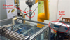 |
Fig. 8 An aviation engine blade is held by single-arm robot for laser ultrasonic testing. |
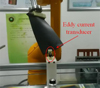 |
Fig. 9 A turbine blade is held by single-arm robot for eddy current testing. |
4 Dual-arm robot holding transducers
The mode of DAR can perform tasks that SAR can not accomplish. Coordinated movement is an important aspect in the research of DAR. Kim [19] presented a dual-arm robot used to collect human demonstration data in the activities of daily livings for machine learning. Cooper [20] from TWI technology center Wales described a robotic inspection system to inspect components with complex geometry. The heart of the system were two 6 DOF robots each capable of working independently and cooperatively. The system was able to manipulate transducers around highly complex shapes at high speed and with great accuracy. Mineo [21] presented a new inspection system comprises two KUKA robot arms. The key novelty was through the accommodation of flexible robotic trajectory planning, coordinated with the NDT data acquisition. The approach provided a pathway for the capability of multiple robot control. Guo [22] established an NDT solution for semi-enclose workpieces based on a dual-robot system of synchronous motion. Experiment results proved that the dual-robot NDT scheme functions well and all hole-shaped artificial defects with diameters ≥3 mm can be detected. Wang [23] developed a dual-robot collaborative machining system for milling of thin-wall parts. The slave robot synchronously followed the master robot and the tools mounted on the flange of the two robots were kept in mirror position based on a novel dynamic model. He [24] presented a systematic three-step approach to designing and programming a dual-arm system, as well as to optimize system performance. The effectiveness of the approach were demonstrated on a physical testbed of two ABB robots and a simulation testbed of two FANUC robots. Wrede [25] set up two Franka Panda robots to performing a peg-in-hole insertion task. The robots' feedback-based trajectories were planned through reinforcement learning and executed by a low-level impedance controller. The approach showed a decrease in process time comparing with classical path planning method.
In this research, dual-arm robot system is capable of adapting to test different types of curved surfaces. The transducers and the testing methods are chosen according to the characteristics of the materials. The software of the testing system produces scan trajectory based on the CAD model of the tested part. Then, testing algorithms and display modes are chosen automatically to satisfy the requirements for rapid testing of the parts with different curvatures, thicknesses, shapes and material properties.
4.1 Configuration of the testing system
The testing system of dual-arm robot holding transducers is suitable for the application that the transducers need to maintain a certain spatial relationships, such as the method of ultrasonic transmission test. The prototype of dual-arm robot holding transducers is shown in Figure 10. Coordinated movement plays an important role to execute efficient and accurate scanning. The system typically employs shelf-based robots as actuator to reduce development costs and time. Additional axis are added to the system to expand the test area. For example, the robot can be installed on a track to test both the open curved surface and the semi-open cylindrical structures.
The configuration of the system is shown in Figure 11. It consists of mechanical structure, hardware equipment and software. The mechanical structure of the system includes two industrial robots, a linear track, a water circulation unit and a workpiece support. The hardware equipment of the system includes an industrial computer, a motion controller, two ultrasonic transducers, an ultrasonic transceiver device, and a high speed A/D conversion card. The software has functions such as system management, ultrasonic transmission and reception, signal acquisition, shape tracking, motion control, signal processing, image display and parameter setting.
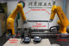 |
Fig. 10 A prototype of dual-arm robot holding transducers. |
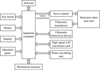 |
Fig. 11 Configuration of the mode that dual-arm robot holds the transducers. |
4.2 Method to plan the scan trajectory
Dual-arm robot is suitable for the testing systems with more than one transducers. Taking ultrasonic transmission testing as an example, it includes a lunch transducer and a receive transducer. A certain amount of wave may be reflected and refracted when passing through the interface. So, the transducers held by the robots need to adjust position and orientation according to the curvature of the surface to ensure receiving sufficient sound energy. The process of scanning the tested part using ultrasonic transmission method is shown in Figure 12. The scan trajectory of the transducer is consistent with the contour of the surface. The sound beam emitted by the lunch transducer is incident on the upper surface along normal direction to reduce reflection and enhance transmission. If the upper surface and the lower surfaces of the structure are not symmetrical, reflection and refraction will occur in the tested material. Direction of the receiving transducer needs to be calculated based on Snell's law, and there is usually a certain degree of deviation between the normal direction of the lower surface and the direction of the receiving transducer to receive more sound energy.
Firstly, serials of discrete points S1 (ui, vj) are generated on the upper surface using CAM software. Normal vectors of the discrete points are calculated to determine the orientation of the launch transducer. Then, discrete points of lower surface are generated also using CAM software. The orientation of the receive transducer are calculated based on Snell's law.
Assuming that the intersection point of the sound beam on the incident surface is S1 (ui, vj), the normal vector of S1 (ui, vj) is calculated using neighbor points S1 (ui+1, vj) and S1 (ui, vj+1 ) according to equation (7):
 (7)
(7)
Similarly, ponits S1 (ui-1, vj), S1 (ui-1, vj-1 ), S1 (ui+1, vj-1 ), S1 (ui-1, vj+1 ), S1 (ui, vj-1 ), S1 (ui+1, vj+1 ) are used to calculate the other three normal vectors n12 (ui, vj), n13 (ui, vj), n14 (ui, vj). Finally, the normal vector nt (ui, vj) is fitted based on nti (i=1, 2, 3, 4):
 (8)
(8)
The sound path from the launch transducer to the surface is S1, then the position and the orientation of the launch transducer is
 (9)
(9)
The position of the receive transducer needs to be determined based on the propagation path of the sound beam. Assuming that the incident point of sound beam is S1 (ui, vj), and the sound beam propagates in the tested material along the vector n1 (ui, vj). The intersection point of the sound beam on the lower surface is noted as S2 (ui, vj). The vector of sound beam out of the lower surface is n2 (ui, vj), which is calculated according to curvature of the surface and the propagation law of sound waves in the material. Assuming that the sound path from the lower surface to the receive transducer is s2, then the position and orientation of the receive transducer is
 (10)
(10)
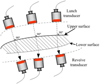 |
Fig. 12 Process of scanning the tested part using ultrasonic transmission method. |
4.3 Implementation examples of the testing system
Internal space of a cylindrical structure is narrow and long, therefor the movement of the robot is restricted and easy to be interfered by inner surface of the cylindrical structure. Additional axis is required to expand the freedom of the robot. The additional axis in this system is a linear track, and one of the robots is installed on the track. The testing process and corresponding C-scan result are shown in Figure 13. Different diameters of holes are drilled on the surface of the structure to simulate discontinuity defects in GFRP specimens. The dark blue area in C-scan image represents the artificial defects in the cylindrical structure. The size and position of the area are consistent with the artificial defects, which proves the availability of the system.
For large open curved surface, the flexibility of the robotic arm can be fully utilized. The coordinate control of the two robots facilitates flexibility of the system. The test process of dual-robot assisted NDT system and corresponding C-scan result are shown in Figure 14. The words “BIT” is an artificial defect on the open curved surface. The artificial defects are displayed in C-scan image clearly and the size is consistent with the actual size.
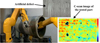 |
Fig. 13 Semi-open cylindrical structure tested by the dual-robot assisted NDT system. |
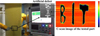 |
Fig. 14 Open curved surface tested by the dual-robot assisted NDT system. |
5 Conclusion
With the development of non-destructive testing technology, there are increasingly requirements for accuracy, efficiency, automation and applicable range of the tested parts. The robot-assisted NDT system is suitable for variable conditions and can complete rapid NDT of different curvatures, thicknesses, shapes, as well as different materials. Comparing with various robot assisted NDT system, it can be found that:
The single-arm robot holding transducer is applicable to test parts with large and curved surface. The tested materials are generally metal. The workspace can be expanded through adding turn table, and it is particularly suitable for the detection of closed curved surfaces.
The single-arm robot holding tested part is suitable for testing parts with small and complex curved surface. It has the characteristic of high detection accuracy and high detection speed. The transducer is fixed and the tested part held by the robot is moved in front of the transducer. The coordinate transformation of this mode is different with the single-arm robot holding transducer.
The dual-arm robot holding transducers is suitable for testing systems that require two probes, such as ultrasonic transmission testing system which two robots are needed to hold two transducers. In addition, coordinated movement needs to be considered for this mode.
The introduction of robots in the NDT process provides convenience for automation, and can effectively expand the application scope of NDT.
Funding
This research was funded by the Research Start-Up Project of NCUT grant number [No. 11005136025XN076-0192025], the Youth Research Special Project of NCUT grant number [No.2025NCUTYRSP006], the Undergraduate Innovation and Entrepreneurship Training Program of NCUT grant number [No. X202510009101].
Conflicts of interest
The authors declare no conflict of interests.
Data availability statement
The datasets used or analyzed during the current study are available from the corresponding author on reasonable request.
Author contribution statement
Conceptualization: H.Z.; Methodology: H.Z.; Resources: Y.L.; Data Curation: Y.C.; Writing − Original Draft Preparation: H.Z.; Writing − Review & Editing: X.S.
References
- K. Isawa, S. Takagi, S. Tosaka et al., Practical scanning SQUID system for nondestructive evaluation, IEEE T. Appl. Supercon. 15, 715–718 (2005) [Google Scholar]
- C. Ji, J.K. Na, Y.S. Lee et al., Robot-assisted non-destructive testing of automotive resistance spot welds, Weld. World. 65, 119–126 (2021) [Google Scholar]
- K. Meng, L. Zhu, Z. Li et al., Terahertz Tomography for Non-Destructive Testing of Objects with Random Surfaces, Perth, Australia, 2024, pp. 1–3 [Google Scholar]
- R. Wang, B. Li, B. Jiang et al., Automated immersion ultrasonic testing technology for debonding defects of the brazed joint of DOME in EAST divertor, Fusion Eng. Des. 176, 113008 (2022) [Google Scholar]
- S.H. Choi, J.Y. Kim, Non-destructive evaluation system of metal materials according to thermal behaviours, Mater. Res. Innov. 18, S2-642- S2–646 (2015) [Google Scholar]
- R. Toman, T. Rogala, P. Synaszko et al., Robotized mobile platform for non-destructive inspection of aircraft structures, Appl. Sci. 14, 10148 (2024) [Google Scholar]
- N.I.L. Ayala, J.C.A. Altamirano, A.M.R. Duke et al., GarRobot: Design, Construction and Control of a Teleoperated Climbing Robot Inspired by Geckos, Niigata, Japan, 2023, pp. 183–188 [Google Scholar]
- S. Wickramanayake, K. Thiyagarajan, S. Kodagoda et al., Ultrasonic thickness measuring in-pipe robot for real-time non-destructive evaluation of polymeric spray linings in drinking water pipe infrastructure, Mechatronics 88, 102913 (2022) [Google Scholar]
- S.K. Chakrapani, V. Dayal, D. Barnard et al., Nondestructive testing of wind turbine blades using air-coupled ultrasonics, Mater. Eval. 73, 1047–1055 (2015) [Google Scholar]
- V. Sinha, A, Srivastava, H.K. Lee et al., A novel method for NDT applications using NXCT system at the Missouri University of Science & Technology, Nucl. Instrum. Meth. A 750, 43–55 (2014) [Google Scholar]
- R. Liu, C. Xu, P. Liu et al., Eddy current pulsed thermography with an inductive heating layer (ECPT-IHL) for subsurface defect detection in GFRP materials, Compos. Part B 290, 111982 (2025) [Google Scholar]
- J. Zheng, W.F. Xie, M. Viens et al., Design of an advanced automatic inspection system for aircraft parts based on fluorescent penetrant inspection analysis, Insight 57, 18–34 (2015) [Google Scholar]
- N.P. Avdelidis, C.I. Castanedo, X.P.V. Maldague et al., Infrared thermography inspection of glass reinforced plastic (GRP) wind turbine blades and the concept of an automated scanning device, Conference on thermonsense: thermal infrared applications XXXV, Maryland, United States, 2013, pp. 87050G [Google Scholar]
- O. Ley, M. Butera, V. Godinez, Inspection of composite structures using line scanning thermography, Conference on thermonsense: thermal infrared applications XXXIV, Maryland, United States, 2012, pp. 835406 [Google Scholar]
- Z. Xiao, C. Xu, D. Xiao et al., An optimized robotic scanning scheme for ultrasonic NDT of complex structures, Exp. Tech. 41, 389–398 (2017) [Google Scholar]
- M. Maciejewski, M. Piszczek, K. Kamiński et al., Robot-based setup for non-destructive testing of composite combat helmets using reflective THz-TDS imaging, in: 49th International Conference on Infrared, Millimeter, and Terahertz Waves (IRMMW-THz), Perth, Australia, 2024, pp. 1–2 [Google Scholar]
- P. Ma, C. Xu, D. Xiao, Robotic ultrasonic testing technology for aero-engine blades, Sensors 23, 3729 (2023) [Google Scholar]
- K.S. Ma, K.J. Lee, J.R. Lee, Development of 3D scan integrated robot arm control for pulse-echo laser ultrasonic testing, Active and Passive Smart Structures and Integrated Systems XVIII, California, United States, 2024, pp. 12946 [Google Scholar]
- J. Kim, S. Heo, S. Kim et al., A twin dual-arm robot testbed to collect the human demonstration data for imitation learning, in: 13th International Conference on Soft Computing and Intelligent Systems and 25th International Symposium on Advanced Intelligent Systems (SCIS&ISIS), Himeji, Japan, 2024, pp. 1–4 [Google Scholar]
- I. Cooper, I. Nicholson, D. Liaptsis et al., Development of a fast inspection system for complex aerospace structure, 6th International Symposium on NDT in Aerospace, Madrid, Spain, 2014 [Google Scholar]
- C. Mineo, S.G. Pierce, B. Wright et al., Robotic path planning for non-destructive testing of complex shaped surfaces, Am. Inst. Phys. 1650, 1977–1987 (2015) [Google Scholar]
- C. Guo, C. Xu, J. Hao et al., Ultrasonic non-destructive testing system of semi-enclosed workpiece with dual-robot testing system, Sensors 19, 3359 (2019) [Google Scholar]
- R. Wang, Y. Sun, Chatter prediction for parallel mirror milling of thin-walled parts by dual-robot collaborative machining system, Robot. CIM-Int. Manuf. 88, 102715 (2024) [Google Scholar]
- H. He, C.L. Lu, G. Saunders et al., Fast and accurate relative motion tracking for dual industrial robots, IEEE Robot. Autom. Let. 9, 10153–10160 (2024) [Google Scholar]
- K. Wrede, S. Zarnack, R. Lange et al., Curriculum design and Sim2Real transfer for reinforcement learning in robotic dual-arm assembly, Machines 12, 682 (2024) [Google Scholar]
Cite this article as: Hanming Zhang, Xizhi Sun, Yongqian Lin, Zhanxin Fu, Tianci Zhang, Yihe Ren, Design and implementation of robot-assisted systems for non-destructive testing, Int. J. Metrol. Qual. Eng. 17, 2 (2026), https://doi.org/10.1051/ijmqe/2025011
All Figures
|
Fig. 1 Configuration of the mode that single-arm robot holds the transducer. |
| In the text | |
|
Fig. 2 Ultrasonic transducer to detect inner defects in wheel hub. |
| In the text | |
|
Fig. 3 Eddy current transducer to detect surface cracks on wheel hub. |
| In the text | |
|
Fig. 4 Ultrasonic transducer to detect residual stress distribution. |
| In the text | |
|
Fig. 5 A prototype of single-arm robot holding tested part. |
| In the text | |
|
Fig. 6 Configuration of the mode that single-arm robot holds the tested part. |
| In the text | |
|
Fig. 7 Comparison of the test sample and the test result. |
| In the text | |
|
Fig. 8 An aviation engine blade is held by single-arm robot for laser ultrasonic testing. |
| In the text | |
|
Fig. 9 A turbine blade is held by single-arm robot for eddy current testing. |
| In the text | |
|
Fig. 10 A prototype of dual-arm robot holding transducers. |
| In the text | |
|
Fig. 11 Configuration of the mode that dual-arm robot holds the transducers. |
| In the text | |
|
Fig. 12 Process of scanning the tested part using ultrasonic transmission method. |
| In the text | |
|
Fig. 13 Semi-open cylindrical structure tested by the dual-robot assisted NDT system. |
| In the text | |
|
Fig. 14 Open curved surface tested by the dual-robot assisted NDT system. |
| In the text | |
Current usage metrics show cumulative count of Article Views (full-text article views including HTML views, PDF and ePub downloads, according to the available data) and Abstracts Views on Vision4Press platform.
Data correspond to usage on the plateform after 2015. The current usage metrics is available 48-96 hours after online publication and is updated daily on week days.
Initial download of the metrics may take a while.