| Issue |
Int. J. Metrol. Qual. Eng.
Volume 7, Number 3, 2016
|
|
|---|---|---|
| Article Number | 306 | |
| Number of page(s) | 8 | |
| DOI | https://doi.org/10.1051/ijmqe/2016022 | |
| Published online | 31 October 2016 | |
Traceability of small force measurements and the future international system of units (SI)
1
Laboratoire Commun de Métrologie: LNE-Cnam,
61 rue du Landy – Case 2LAB10,
93210
La Plaine Saint-Denis, France
2
Laboratoire National de Métrologie et d'Essais: LNE,
1 rue Gaston Boissier,
75015
Paris, France
⁎ Corresponding author: This email address is being protected from spambots. You need JavaScript enabled to view it.
Received:
11
September
2016
Accepted:
13
September
2016
Abstract
The unit of force is connected to the international prototype of the kilogramme, unit of mass in the international system of units (SI), via dead weight machines using calibrated masses. However, forces below 10 μN, ubiquitous in nature and in some devices cannot be measured with a traceability to the SI. The measurement, with the uncertainty of these forces has implications for both basic and applied science. Today, many emerging sectors in micro/nanotechnology and biotechnology have started producing and using systems to implement low forces that, for various reasons, require them to be traceable. Also, the revision of the SI, scheduled for 2018 year, of linking the definitions of the kilogramme, the ampere, the kelvin and the mole to fixed numerical values of fundamental constants, has aroused particular interest in the measurement and calibration of small forces. In this paper, we will give some indications of the state of the art on the small force with a focus on the development of a force sensor using a photoelastic crystal as a monolithic solid-state laser. Basically, the force to be measured is applied to the crystal induces a birefringence in the laser medium which in turn manifests itself by the appearance of a splitting between the frequencies associated with the two polarization components of the oscillating laser mode. This difference is then exploited because, within the elastic limit of the crystal, it is proportional to the force acting on the laser.
Key words: international system of units (SI) / solid state laser / birefringence / small force / mass standard
© EDP Sciences, 2016
1 Introduction
Force is a quantity derived from mass and therefore traceable to the kilogramme standard. In recent years, much works has been undertaken to implement different techniques for measuring forces with good accuracy and especially for those whose value is below 10 μN. The first “passive” optical sensors using optical fibers integrating of the MEMS (Micro-Electro-Mechanical System) or Bragg gratings proved to be unsuitable owing to of their high hysteresis and the complexity of their response [1–3]. Other more promising developments are under way which relate in particular to the use of electrostatic balances [4–6]; microbalances with electromagnetic compensation [7] or “active” optical sensors based on the photoelastic effect in a solid state laser [8–10].
Today many devices are able to measure or detect forces with a resolution, which can be much better than the nanonewton.
However, on an international level, there are still no calibration and measurement capabilities (CMCs) for forces below 0.1 N [11]. For the moment, measurements of force between 0.1 N and 10 μN are carried out, with a connection in traceable way to the basic units of the international system of units (SI), only by using standard masses, which is not really useful for establishing CMCs. On the other hand, force measurements below 10 μN are performed without any traceability to the SI. Today, relatively compact, almost miniature, force sensors intended for measurements (both in compression and traction) of forces below the Newton have begun to appear on the market. However, their measurement range remains close to the Newton. At lower level of forces, balances can be used, but in practice, their size and fragility are a great disadvantage.
Recent developments, in various fields of nanotechnology, have highlighted the growing importance not only of miniature force sensors but also of the connection of theirs responses to the SI.
Therefore, industrial manufacturers of instrumentation for the measurement of small forces have started to pay particular attention to the calibration of their devices and their associated uncertainties. Indeed, the reproducibility of experiments involving measurements of small forces is difficult to check as it involves instruments based on various methods.
The objective of this paper is to identify not only the techniques already implemented and the opportunities that might arise from traceable measurement devices for small forces but also artefacts that could be used to ensure the transfer of the primary references to the devices requiring calibration.
The possibilities of calibration of the forces below one Newton in different laboratories of metrology as well as an outline of work in the field of weak forces are given in Section 2. A brief review of the theory of birefringence, in a solid-state laser, induced by mechanical stress and its impact on the components of the polarisation of the oscillating laser mode is the subject of Section 3.
Section 4 presents the experiment using photoelastic force sensors, developed at the Joint Laboratory of Metrology LNE-CNAM, and some significant experimental results regarding the sensitivity of this type of sensor. The contribution of this work and the prospects concerning the instrumental challenge for the realization of primary references as well as transfer devices to make traceable measures of weak force are summarized in Section 5.
2 The place of the small forces
The development of a transfer artifact to provide traceability of force measurements in the range of millinewton to micronewton is motivated by the growing need in certain industrial sectors (instrumented indentation, Micro Electro Mechanical Systems, etc.) but also for the development of some emerging sectors in medicine, especially for miniature devices used to handle or to manipulate fragile biological objects.
Figure 1 gives some scales, areas of use with the orders of magnitude of the force associated with some simple devices.
 |
Fig. 1 Some fields using various ranges of forces. |
3 State of the art
On an international level, the current situation of CMC's of the national laboratories of metrology give no possibility for forces below 0.1 N.
Table 1 gives the values of the minimal forces in CMC's of a number of Europeans laboratories. These data correspond to the values appearing in the database of the key comparisons (November 2014) of the Bureau International des Poids et Mesures. The relative uncertainties associated with these minimal values of CMCs lie between 10−1 and 10−4.
Minimal forces (CMCs) connected to SI units by some National Laboratories of Metrology.
3.1 Force generated with dead weight
The most current devices in mass laboratories rely on the use of balances with electromagnetic compensation and series of mass standards, connected beforehand to the SI units of the kilogramme. These means are exploited in the field of forces because the most intuitive method to produce a force is by using a proof mass in the gravitational field of the Earth.
A force Fdw called a “dead weight” or weight of the proof mass is thus generated in the gravitational field of the Earth. It is given by:
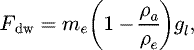 (1)
where me is the mass of the standard and ρe its density, ρa and gl represent respectively the density of the ambient air and the intensity of the local gravitational acceleration.
(1)
where me is the mass of the standard and ρe its density, ρa and gl represent respectively the density of the ambient air and the intensity of the local gravitational acceleration.
Equation (1) implies for a standard of mass 100 mg in the gravitational field of the laboratory, a dead weight of 9.8094 × 10⁻⁴ N with an uncertainty of about 10 nN [12].
In terms of mass standards, the smallest weight value in the CMC of NMI is 1 mg. This is the case for those laboratories listed in Table 1, but also for all other. This mass standard produces a force (dead weight) of about 10 μN. It should be noted that micro-mass standards having nominal values between 900 and 100 μg have been produced at LNE [13,14] and are used as references for calibration. Since then, other laboratories are engaged in the realization of such standards (NPL, PTB, INM-Romania, METAS, etc.) and that are also partially commercialized.
Thus, the method based on the use of mass standards in the dead weight machines, like the one in Figure 2, for traceability of force and covers the range from 1 N to several meganewtons.
In principle, this technique could be used for smaller dead weights; without any scientific or technological difficulty, down to about ten micronewtons. Below this limit, however, it becomes relatively difficult to implement because of small dimensions and the geometrical shapes of micro-masses standards causing relatively high uncertainties in the weight measurement. We shall see hereafter that small dead weights such as transfer are usable in combination with high-resolution balances (on the scale of 0.1 μg).
3.2 Measuring forces
At the national level (LNE-France), the possibilities accredited by the French organization for accreditation (COFRAC) according to ISO 17025 span the range from 1 N to 9 MN.
The LNE reserves the right to change its CMCs according to the needs expressed by of industry to go down to 10 μN by the dead weight technique. This possibility could be quickly implemented, thanks to its competence of development of new methods or new means of calibration, a competence recognized by COFRAC.
Currently, the department “forces and associated quantities” of LNE issues certificates of calibration beyond 1 N. With the resources available, in the laboratory of “masses and derived quantities”, the forces department is able to extend this kind of calibration to the lower values of about 10 μN, by the use of a mass standard of 1 mg with an uncertainty of 0.6 μg.
The uncertainty in the force, generated in this way is then about 10 nN. Such means would make it possible to calibrate force sensors in the laboratory that would then be used to make traceable measurements on site. These might be deformation gauge sensors or high resolution balances which are of course sensitive to the force applied to them.
However, in the field of forces, good practices recommend the calibration of the force sensors in the place of their use.
Also, as it is simple for the user to acquire mass standards for this range, and to calculate the generated forces, the development of CMCs has not been very useful to date for the range 1 N to 10 μN. On the other hand the problems persists for the range of the forces lower than 10 μN.
4 Electromechanical devices dedicated to small forces measurement
4.1 Primary standards
Some international laboratories (NIST, NPL, PTB, KRISS) in the world have sought to develop references for small forces based on electromechanical devices.
For more than 10 years, the National Institute of Standards and Technology (NIST), in the United States, works on a project of a “nanoforce balance” to cover the range of force going from 1 nN to 1 μN with a relative uncertainty of about 0.1% for a force of several nanonewtons [16–18].
This electrostatic balance is founded on the measures of electrique voltage, electric capacity and displacement which are traceable to the SI units with great accuracies. It should be noted that this laboratory is also developing a “watt balance” dedicated to the connection of a standard of mass with the Planck constant from the point of view of the revision of the current system of units (SI). The capacitor consists of two concentric electrodes. The internal electrode, movable along the vertical axis, is guided by flexible suspension elements.
The most recent results [18,19] mention principal limitations dependent on the one hand, on the stiffness of the system of suspension and on the other hand, on the sensitivity of the system and the geometry of the capacitor.
Figure 3 gives the schematic principle of an electrostatic balance in equilibrium. A vertical force applied to the plate moves the bending element in the same direction. This displacement, measured by a differential plane mirror interferometer, is converted by a control system against a voltage feedback.
The force of negative feedback is then produced by the potential difference across the capacitor plates oriented vertically.
The electric force thus generated, in response to the load along the axis of the balance is given, as a function of the electrical quantities, by the relation:
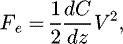 (2)
where dC is the change in capacitance, measured for a displacement dz given the overlap of the electrodes, and V is the applied electrical voltage.
(2)
where dC is the change in capacitance, measured for a displacement dz given the overlap of the electrodes, and V is the applied electrical voltage.
This type of balance acts as a primary force standard. It requires an artifact of transfer of the reference, given by the “balance” to the target instrument to be calibrated.
The National Physical Laboratory (NPL), in the United Kingdom, has also designed a balance for small forces, called LFB “Low Force Balance” which works on the same principle as that of the NIST balance. However, it uses a planar condenser with four electrodes allowing for choice of the direction of the force exerted on a dielectric plate suspended on the guidance system according to the applied voltage (dielectric mobile). The selected configuration would allow calibration both in compression as well as in traction. The expected dynamics will correspond to a field of forces ranging between 10 μN and 1 nN, with a resolution of a few tens of piconewtons [19]. The interest of this project is its focus on a field non-traceable to date and has a slight overlap with the method of the dead weights. It also has the advantage of carrying out tractive efforts.
The Korea Research Institute of Standards and Science (KRISS), in the South Korea, has developed an electrostatic device having also a coaxial condenser. The suspension system relies on the use of flexible blades ensuring the compensation of the suspended mass [20]. The sensitivity of this device is of the order of 1 μN.
4.2 Transfer devices
The Physikalisch Technische Bundesanstalt (PTB), in Germany, has various electromagnetic weighing devices for a range of force higher than 0.1 mN.
The prototype device has a magnet-coil set, designed to cover the field of the forces ranging between 100 μN and 0.1 N [21]. Its use remains conditioned by its connection to the SI units via mass standards. Finally, the PTB in collaboration with Tianjin University (China), is seeking to produce force transfer artefacts based on the use of MEMS [22].
For traceable measurement of advanced stiffness AFM, KRISS has developed a device based around a commercial “microbalance” with electromagnetic compensation which is calibrated beforehand by means of mass standards [23]. The tip is mounted on a vertical translation stage which can accurately measure the displacement and the free end of the tip is brought to rest on a small sphere placed on the plate of the microbalance (Fig. 4).
The bearing force of the tip on the sphere generates a reaction of the electromagnetic force compensation system of the microbalance which gives an indication in mass. This is directly convertible into force by multiplying the conventional value either spoke, or by a locally determined value of the acceleration of gravity. Stiffnesses of about 0.07 Nm−1 for the force applied in the order of 500 nN were measured with a relative uncertainty of 1% [24].
The other way is to use an electromagnetic balance based on the principle of a watt balance. The measurement of the unknown force is performed using the Lorentz force, connected as a preliminary to a dead weight, to balance the system. Preliminary studies were carried out at LCM-Cnam, using a prototype similar to that of the watt balance as shown in Figure 5. The first tests relating to the study of the sensitivity of this balance are very encouraging [25].
 |
Fig. 5 Prototype of the electromagnetic force balance at Joint Laboratory of Metrology (LNE-Cnam). |
5 Elastic sensor device
5.1 Photoelastic effect in a solid laser
The birefringence induced in the amplifying medium of a monolithic solid laser, when the latter is subjected to a mechanical constraint, appears by different index of refraction according to whether the polarization of the wave which crosses the crystal is in the direction of application of the force or in the orthogonal direction. This birefringence is particularly important when the applied force is parallel to the direction of a principal axis of constraints (this is the case of the photoelasticity in two dimensions). In this configuration, the principal directions of the ellipsoid of the refractive indexes coincide with those of the constraints.
The expression of the birefringence induced in the laser medium, represented by the optical relation of constraint, is given by the classical law of Wertheim [26]:
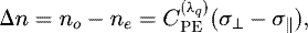 (3)
where σ|| and σ⊥ are the main stresses induced in the center of the laser medium along directions parallel and orthogonal to the external force.
(3)
where σ|| and σ⊥ are the main stresses induced in the center of the laser medium along directions parallel and orthogonal to the external force.
 , is the constant of photoelasticity of the laser crystal (Nd:YAG). This constant depends weakly on the wavelength λq associated with the longitudinal laser mode of order q.
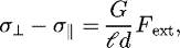
In the situation when the external force is in a diametrical plane of the laser crystal (as indicated in Fig. 6), containing the both directions of principal stresses, the converting force in terms of internal stresses can be written [27] as:
 (4)
where
(4)
where  and d are the length and the diameter of the monolithic solid Nd:YAG laser; G is a factor whose value depends on the conditions of geometric alignments of the Nd:YAG rod relative to the laser beam used to optically pump the laser medium.
The effect of birefringence on the oscillating laser mode will correspond to the appearance of a phase difference between the two orthogonal polarizations of the laser mode. As shown in Figure 7, the shift of the phase is the difference between the frequencies of the two orthogonal polarizations components of the oscillating laser mode. It is given by:
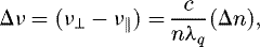 (5)
where n is the refractive index of the Nd:YAG in the absence of any constraints and c the speed of light in vacuum.
(5)
where n is the refractive index of the Nd:YAG in the absence of any constraints and c the speed of light in vacuum.
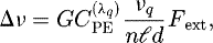
This frequency difference is then expressed as a function of the external force by the following relationship:
 (6)
(6)
 is the frequency of laser emission.
In the ideal case, the dimensions of the optical pump laser beam must be small compared with the diameter of the Nd:YAG crystal and moreover the pump beam centered on his axis of revolution. This dual condition becomes relatively critical and consequently difficult to achieve when monolithic lasers miniature is used.
Considering the configurations of the two sensors already studied and the available values of various constants, the theoretical sensitivity Δv/Fext, is expressed simply by [12]:
-
 ; for sensors such as
  ;
; -
 ; for sensors such as
  .
.
For reasons of convenience, the quantities  and d, in the above expressions of sensitivity, are expressed in millimetres so as to yield a sensitivity in MHz × N−1.
 |
Fig. 6 Orientation and major axes of the Nd:YAG crystal. |
 |
Fig. 7 Effect of the applied force on the polarization components of the laser mode. |
5.2 Experimental apparatus
The diagram of the experiment with the principal elements of the device is shown in Figure 8. The laser crystal is mounted on an aluminum block whose temperature is stabilized around 18 °C within ±0.02 °C by using a PID control loop based on a Peltier element and a thermistor.
Qualitative measurements show that a temperature controlled and mechanically rigid assembly are essential for the stability of the beat frequency signal and therefore the repeatability of measurements.
Indeed, the emission frequency of a solid-state laser is very sensitive not only to changes in the amplifier medium temperature, but also to mechanical vibration. The application of force is performed by a successive series of deposit-withdrawal of a mass standard (weight in the gravitational field) on the upper part of the laser crystal.
Figure 9 shows a photograph of a part of the experimental device. One can distinguish: 1 – opto-mechanical system of the laser diode at 808 nm for pumping Nd:YAG laser; 2 – crystal holder at controlled temperature; 3 – optical filter; 4 – lens; 5 – pinhole; 6 – polarizer; 7 – fast detector.
 |
Fig. 8 Diagram of the photoelastic force sensor. |
 |
Fig. 9 Photography of the photoelastic force sensor. |
5.3 Response and sensitivity of the photoelastic force sensor
To characterize the sensor on a given loading area, masses standard were used. Small masses are placed directly on the laser rod. The uncertainty of repeatability associated with each measurement is evaluated starting from series of measurement with the same dead weight for approximately ten deposit-withdrawals of the corresponding mass standard.
The points indicated in Figure 10 give, for the two force sensors studied, the difference in frequency between the two polarization components of the laser mode, when they are under the action of a mass ranging between 0 and 2 g. The use of higher masses (>500 g) is completely possible and easy to make if one remains within the elastic limit of Nd-YAG crystal.
The curves in the dotted lines in Figure 10 correspond to the linear fits of the experimental values obtained with each of the two laser sensors considered in the laboratory. All measurement results obtained show that the response of this type of sensor is almost linear in the range of weak forces (domain of elastic behavior of the crystal). For the two sensors studied, the experimental sensitivities are:
-
S1 = (0.558 ± 0.008) MHz × g−1; for the sensor of (2 × 3) mm;
-
S2 = (0.297 ± 0.012) MHz × g−1; for the sensor of (4 × 4) mm.
We conducted a series of measures with the sensor (2 × 3) mm when under the influence of a particular standard mass. Table 2 gives the frequencies of the values of the beat signal and the repeatability uncertainties observed when the latter is successively loaded or not by masses of 1 g and 100 mg.
The value of the local gravitational field, measured in the laboratory is:  .
.
The dead weight associated with standard masses of 1 g and 0.1 g are given by relation (1) with an uncertainty less than 50 nN [12].
The force applied to the crystal is determined from successive measurements of the beat frequencies  (unloaded sensor) and
  (sensor loaded) and the experimental value of sensitivity. It is calculated from the following relationship:
 (7)
(7)
In the range of constraints considered, the hysteresis effect is almost zero and consequently beat frequencies  and
and  are only weakly correlated. In Table 3, are given the values of the dead weight according to equation (1) and those obtained using the photoelastic force sensor of dimensions (2 × 3) mm.
We noted that for low dimensions of the photoelastic sensor, technical difficulties appear when it is a question of charging with small masses. Moreover, as Table 3 shows, the relative variation of the weight measured to that given by relation (1) increases slightly.
The principal limitation of this device is associated with the reproducibility of the method of application of the force on the laser crystal. Also, the presence of an offset, generated by residual stresses than can vary over the course of time, requires a point of reference for each series of measurement. Nevertheless, the wide range of linearity of this type of force sensor and it low response time make it favourable compared to other methods.
Also, it remains interesting to miniaturize it, on the one hand to increase its sensitivity and to reach weaker forces and on the other hand, to connect it to references other than mass standards.
The use of this sensor as a transfer tool in the comparisons between laboratories is completely possible because it can cover a range of measurement which overlaps with those observed with other devices.
Figure 11 provides an overview of the measuring range that can be achieved with devices either existing or under development.
From the point of view of the redefinition of SI units, starting from the fundamental constants values [28], calibration of the force within new SI should not rely directly and solely on the use of mass standards. This approach is particularly justified in the field of the small forces, because of the uncertainties generated by the use of standards masses smaller than 1 mg. The approach consisting in using the electrostatic force to generate a traceable means, starting from measurements of electric quantities, is particularly interesting and promising so technical developments has been made. The other approach consists in developing transfer standards, likely to be miniaturized, such as sensors based on assembly of MEMS, MOEMS (Micro-Opto-Electro Mechanical Systems), photoelastic crystal. Once finalized, these types of devices could constitute a future traceability chain for measurements of forces over a wide range.
 |
Fig. 10 Responses of photoelastic force sensor: results for two geometric configurations of the sensitive element. |
Beat frequencies observed with the sensor (2 × 3) mm loaded successively by two masses standards.
Local weight and dead weights measured with the sensor.
 |
Fig. 11 Review of range associated to some devices dedicated to forces measurements. |
6 Conclusion
The research tasks undertaken by many metrology labs show first, a diversity of experimental approaches to make traceable measurements of small force and secondly, the need for having transfer artefacts from the reference standard for force to the system to be calibrated.
The studies of sensitivity of the photoelastic force sensor, made with two sensors having sensitive elements of different dimensions, have made it possible to identify the various parameters that affect the characteristics of this type of sensor.
This work has also shown that the miniaturization of the sensor facilitates the treatment of the signal of beat frequencies and makes it possible to increase to a significant degree the sensitivity of the sensor and thereby extend the effective range of measurement towards low values. However, the challenges related to optical alignments and the degradation of reproducibility of the measurements show that the miniaturization of an opto-mechanical device will not consist merely in decreasing dimensions of the sensitive element of the force sensor. In fact, it is necessary to integrate the sensitive element of the sensor and the other opto-mechanical elements in a rigid and compact block to reduce fluctuations and drifts of the beat frequency signal. Hence, with a miniature Nd:YAG crystal (1 × 2) mm, forces lower than 10 μN can be detected and measured. In summary, this type of force sensor has all the conditions to be realized in a configuration of reduced volume.
Acknowledgments
This work was supported by the “Laboratoire National de métrologie et d'essais” (LNE) and the Conservatoire National des Arts et Métiers (Cnam) within the framework of the joint laboratory of metrology (LCM). The authors would like to thank all of their co-workers at LCM who participated in this research work but more particularly D. Mark Plimmer for his critical and constructive reading of the manuscript.
References
- A. Barlow, D.-N. Payne, IEEE J. Quant. Electr. 19, 834 (1983) [CrossRef] [Google Scholar]
- X. Ni, M. Wang, X. Chen, Y. Ge, H. Rong, Meas. Sci. Technol. 17, 2401 (2006) [CrossRef] [Google Scholar]
- D.-V. Dao, K. Nakamura, T.-T. Bui, S. Sugiyama, Adv. Nat. Sci: Nanosci. Nanotechnol. 1, 013001 (2010) [CrossRef] [Google Scholar]
- R.-K. Leach, S. Oldfield, S.-A. Awan, J. Bmackburn, J.-M. Williams, NPL report DEPC-EM 001, 2004 [Google Scholar]
- G.-L. Miller, J.-E. Griffith, E.-R. Wagner, D.-A. Grigg, Rev. Sci. Instrum. 62, 705 (1991) [CrossRef] [Google Scholar]
- J.-R. Pratt, J.-A. Kramar, in Proceedings of the XVIII IMEKO World Congress, 17–22 September, Rio de Janeiro, Brazil (2006) [Google Scholar]
- C. Diethold, M. Kühnel, F. Hilbrunner, T. Fröhlich, E. Manske, Measurement 51, 343 (2014) [CrossRef] [Google Scholar]
- W. Holzapfel, W. Settgast, Appl. Opt. 28, 4585 (1989) [CrossRef] [PubMed] [Google Scholar]
- W. Holzapfel, S.-N. Rube, M. Kobusch, Measurement 28, 277 (2000) [CrossRef] [Google Scholar]
- N.-E. Khelifa, in Proceedings of the 20th International Metrology Symposium, November 12–15, Croatia (2008) [Google Scholar]
- WEB site of the BIPM. http://kcdb.bipm.org/appendixC/search.asp?sservice=M/Force.4.3 [Google Scholar]
- N.-E. Khélifa, M. Himbert, Sens. Transducers 184, 19 (2015) [Google Scholar]
- T. Madec, G. Mann, P.A. Meury, T. Rabault, Metrologia 44, 266 (2007) [CrossRef] [Google Scholar]
- T. Madec, G. Mann, P.A. Meury, N.-E. Khelifa, Revue française de métrologie 27, 29 (2011) [Google Scholar]
- Étalons et unités de mesure- Les bases de la métrologie en France − mise en pratique du système International d'unités- BNM & AFNOR, 27, 1996 [Google Scholar]
- J.-R. Pratt, D.-B. Newell, E.-R. Williams, D.-T. Smith, J.-A. Kramar, in Proc. of the 2nd Euspen International Conference, Turin, Italy, 27–31 May (2001) [Google Scholar]
- J.-R. Pratt, D.-B. Newell, J.-A. Kramar, Vdi-Berichte NR 1685, 77 (2002) [Google Scholar]
- J.-R. Pratt, D.-T. Smith, D.-B. Newell, J.-A. Kramar, E. Whitenton, J. Mater. Res. 9, 1 (2004) [Google Scholar]
- C.-W. Jones, R.-K. Leach, National Physical Laboratory, NPL, Report ENG 5, 2008 [Google Scholar]
- I.-M. Choi, D.-J. Choi, S.H. Kim, Jpn. J. Appl. Phys. 41, 3987 (2002) [CrossRef] [Google Scholar]
- C. Schlegel, O. Slanina, G. Haucke, R. Kumme, Measurement 45, 2388 (2012) [CrossRef] [Google Scholar]
- S. Gao, Z. Zhang, Y. Wu, K. Herrmann, Meas. Sci. Technol. 21, 015103 (2010) [CrossRef] [Google Scholar]
- M.-S. Kim, J.-H. Choi, J.-H. Kim, Y.-K. Park, Meas. Sci. Technol. 18, 3351 (2007) [CrossRef] [Google Scholar]
- M.-S. Kim, J.-R. Pratt, U. Brand, C.-W. Jones, Metrologia 49, 70 (2012) [CrossRef] [Google Scholar]
- P. Pinot, Private communication: Journée organisée par le GT2 du Club nanoMétrologie: thématique “Métrologie des très faibles masses et très faibles forces”, Paris (2015) [Google Scholar]
- M.G. Wertheim, Ann. Chim. Phys. 40, 156 (1854). [Google Scholar]
- M.-M. Frocht, Phtoelasticity (John Wiley and Sons, London, 1941), 8th ed., p. 144 [Google Scholar]
- P. Richard, J. Ullrich, Joint CCM and CCU roadmap towards the redefinition of the SI in2018, approved by the CIPM on 13 November 2013 [Google Scholar]
Cite this article as: Naceur-Eddine Khelifa, Philippe Averlant, Marc Himbert, Traceability of small force measurements and the future international system of units (SI), Int. J. Metrol. Qual. Eng. 7, 306 (2016)
All Tables
Minimal forces (CMCs) connected to SI units by some National Laboratories of Metrology.
Beat frequencies observed with the sensor (2 × 3) mm loaded successively by two masses standards.
All Figures
|
Fig. 1 Some fields using various ranges of forces. |
| In the text | |
 |
Fig. 2 Diagram of a force machine with dead weights [15]. |
| In the text | |
 |
Fig. 3 Diagram of electrostatic balance of NIST [17]. |
| In the text | |
 |
Fig. 4 Schematic diagram of the force machine in the range of 100 μN–100 mN, developed at PTB [21]. |
| In the text | |
|
Fig. 5 Prototype of the electromagnetic force balance at Joint Laboratory of Metrology (LNE-Cnam). |
| In the text | |
|
Fig. 6 Orientation and major axes of the Nd:YAG crystal. |
| In the text | |
|
Fig. 7 Effect of the applied force on the polarization components of the laser mode. |
| In the text | |
|
Fig. 8 Diagram of the photoelastic force sensor. |
| In the text | |
|
Fig. 9 Photography of the photoelastic force sensor. |
| In the text | |
|
Fig. 10 Responses of photoelastic force sensor: results for two geometric configurations of the sensitive element. |
| In the text | |
|
Fig. 11 Review of range associated to some devices dedicated to forces measurements. |
| In the text | |
Current usage metrics show cumulative count of Article Views (full-text article views including HTML views, PDF and ePub downloads, according to the available data) and Abstracts Views on Vision4Press platform.
Data correspond to usage on the plateform after 2015. The current usage metrics is available 48-96 hours after online publication and is updated daily on week days.
Initial download of the metrics may take a while.